

Content last revised on October 24, 2026
FZ600R12KP4 Circuit Protection & Reliability: Baseplate Isolation Testing
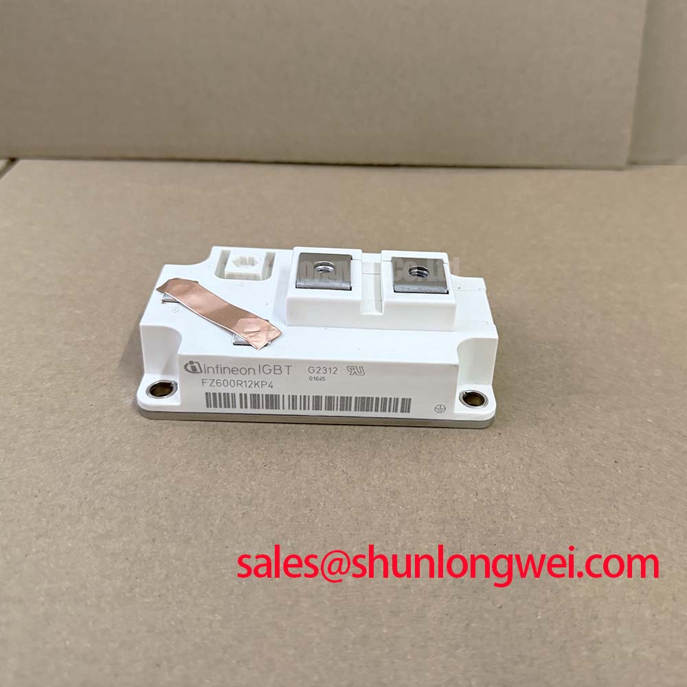
Check terminal polarity before testing: FZ600R12KP4 | Infineon IGBT module | 1200 V collector-emitter rating | 600 A at a case temperature of 100°C | 62 mm package | Official Specification values.
I first separate the power terminals from the driver and external buswork, then identify collector, emitter, and gate connections against the terminal drawing. This prevents parallel circuit paths from confusing incoming inspection. With the gate held at emitter potential using an ESD-safe procedure, a current-limited diode-mode check across the collector-emitter terminals can establish polarity-dependent conduction behavior. Record meter type, lead orientation, and module temperature; compare results with an accepted reference under matching conditions rather than imposing a universal forward-voltage pass band.
💡 Bench Tip: Discharge the DC link and use ESD-safe gate handling before connecting test leads or comparing cold-state readings.
Design Consideration: terminal-to-baseplate insulation assessment requires its own approved test procedure. Insulation resistance and dielectric withstand are different measurements: a resistance reading does not establish breakdown voltage, and a withstand test is not a search for destructive breakdown. Select test voltage, duration, terminal grouping, and acceptance criteria from the applicable manufacturer instructions and equipment service requirements. Disconnect electronics that could be exposed through the test connections.
Before applying the approved test, inspect accessible insulating surfaces for moisture, conductive dust, tracking marks, and contamination around terminal supports. Clean and dry these surfaces using an approved process, then document the test conditions. Surface leakage can influence the reading without identifying an internal defect. Preserve the equipment’s specified creepage and clearance distances when reinstalling busbars; the module voltage rating alone does not establish cabinet spacing or insulation compliance.
The Infineon IGBT Modules & Discretes Official Portfolio provides manufacturer context for the device family; model-specific insulation limits belong to the individual module documentation.
FZ600R12KP4 Thermal-Electrical Optimization: Preventing Spurious Power-Up Shoot-Through Practical Tuning
Establish a defined gate-off state before enabling the DC link, and observe what happens when auxiliary driver power rises, falls, or becomes interrupted. Design Consideration: undervoltage lockout should inhibit switching whenever the driver cannot maintain its intended output state. Where the selected driver uses negative turn-off bias, its magnitude and sequencing must remain compatible with the module’s gate limits and the equipment’s validated driver design.
Capture gate-emitter voltage at the module terminals rather than relying only on the controller command. Probe placement and measurement-loop pickup matter when evaluating apparent gate spikes. Miller coupling can produce gate disturbance during collector-voltage transitions; reverse-transfer capacitance and Miller plateau charge describe related behavior but are not interchangeable quantities. Evaluate gate impedance, return routing, and any active Miller clamp against the measured disturbance.
Design Consideration: if the existing driver uses bootstrap power, assess charge consumption over its longest interval without recharge. Include gate charge at the operating conditions, driver quiescent current, leakage, and usable supply excursion before undervoltage lockout. Bootstrap feasibility depends on the switching pattern; capacitor enlargement alone cannot resolve an operating state that provides no adequate recharge opportunity.
Official Specification: typical collector-emitter saturation voltage is 1.70 V at a junction temperature of 125°C. This is a test-point characteristic, not a guaranteed voltage drop throughout operation. The specified operating junction-temperature ceiling is 150°C. For thermal assessment, use the applicable characteristic curves and thermal data alongside measured case temperature, switching losses, and the installed cooling interface.
FZ600R12KP4 Circuit Protection & Reliability: Calibrating Derating Guidelines and Mismatched Parameters
Compare paralleled current paths at equivalent temperature and gate drive before interpreting unequal current as a module fault. Design Consideration: a positive saturation-voltage temperature coefficient can assist steady-state sharing where the device characteristic curves demonstrate that behavior. It does not guarantee balance across every current level or compensate for unequal busbar resistance, cooling contact, or gate-drive timing.
The 600 A rating at a case temperature of 100°C is an Official Specification with a defined thermal boundary. Assess the actual current waveform, cooling conditions, and junction-temperature excursion together. For regenerative braking-chopper evaluation, distinguish the module’s switching and conduction loading from the braking resistor’s energy-absorption capability. Resistor temperature, chopper duty, and DC-link behavior remain equipment-level checks.
For compatibility assessment, high-speed rail and heavy freight locomotive traction inverter repairs require review of the original voltage class, circuit position, terminal arrangement, cooling assembly, and protection coordination. The FZ600R65KF2 should be treated as a separate comparison candidate, not a verified direct replacement for FZ600R12KP4. Similar naming does not establish electrical, mechanical, or driver interchangeability.
Design Consideration: preserve symmetrical power paths and gate-return routing when evaluating dynamic sharing. In bidirectional DC-DC battery charge/discharge service, assess repeated load transitions and the resulting temperature excursions rather than assigning a service-life figure from the maximum temperature rating. The distributor’s Power Electronics Masterclass offers broader selection and reliability context; it is not a substitute for model-specific qualification.
FZ600R12KP4 Thermal-Electrical Optimization: Mitigating Hard Switching Transients via Practical Tuning
Measure collector-emitter overshoot and gate behavior during controlled switching before altering the protection network. Design Consideration: reduce commutation-loop inductance through compact outgoing and return paths, preserving the required electrical clearances. Laminated busbar geometry can support this objective, but its effectiveness depends on the complete current loop, including capacitor and module connections.
Official Specification: the supplied short-circuit current value is 2400 A. Treat it as a condition-dependent short-circuit characteristic, not an allowable continuous current or proof that an arbitrary fault duration is safe. Coordinate detection, propagation delay, and current extinction with the applicable short-circuit safe operating area and its stated voltage, temperature, and gate-drive conditions.
Design Consideration: distinguish turn-on into an existing short circuit from a fault developing during conduction, because the detector encounters different initial waveforms. Review desaturation blanking against normal turn-on behavior without allowing it to conceal a developing fault. Where a driver provides two-stage or soft turn-off, assess the tradeoff between limiting inductive overshoot and extending fault-current dissipation. Active clamping also requires evaluation of the resulting voltage and energy stress.
The Infineon High Power Semiconductor Solutions portfolio provides manufacturer-level context for complementary power and driver technologies. For the installed FZ600R12KP4, complete the protection check by recording peak collector-emitter voltage, gate excursion, fault-response timing, and driver recovery behavior under the equipment’s approved controlled-test procedure.