Content last revised on March 13, 2026
Optimizing Power Density: The Strategic Role of the Mitsubishi CM600DU-24F in Modern Inverters
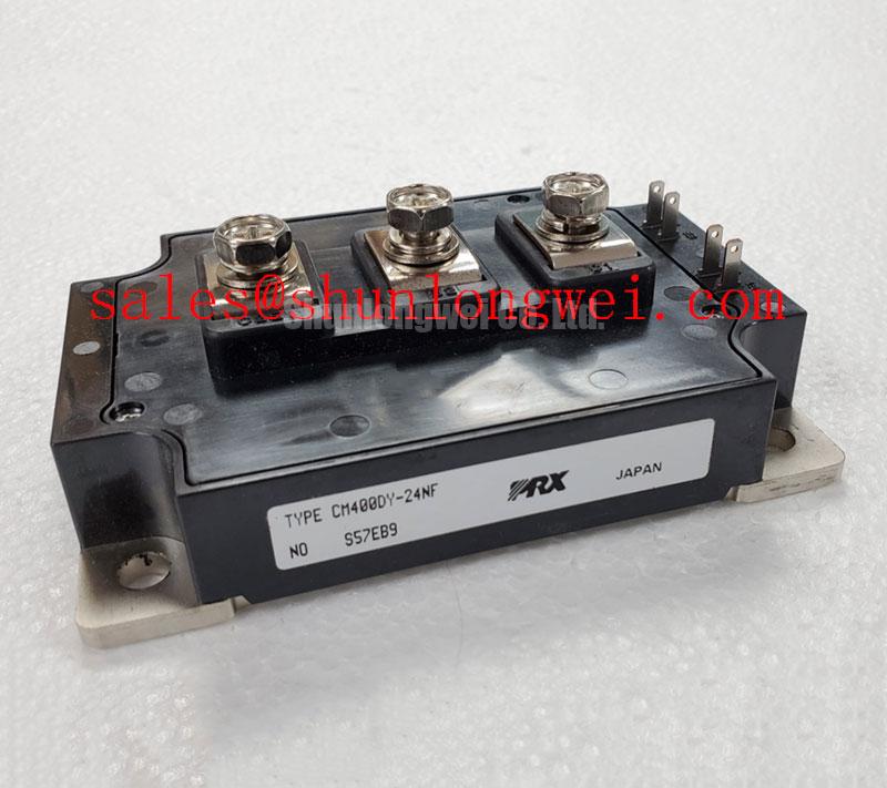
The Mitsubishi CM600DU-24F represents a cornerstone in high-power industrial electronics, delivering a robust 1200V and 600A rating within a dual-element configuration. Designed to minimize power dissipation while maximizing current throughput, this module empowers engineers to develop highly efficient power conversion systems. Key benefits include a significant reduction in switching losses and a simplified mechanical layout, which directly translates to reduced system-level thermal overhead. For industrial drives prioritizing long-term thermal margin and switching precision, the CM600DU-24F is the definitive component for high-current 400V AC applications.
Key Parameter Overview
Decoding the Specs for Enhanced Thermal Reliability
The technical architecture of the CM600DU-24F is built around the 4th Generation Trench Gate CSTBT™ (Carrier Stored Trench-Gate Bipolar Transistor) technology. This design philosophy focuses on achieving an optimal balance between conduction losses and switching speeds.
| Parameter | Technical Value | Engineering Significance |
|---|---|---|
| Collector-Emitter Voltage (Vces) | 1200V | Provides essential safety margin for 400V-480V AC line rectified DC buses. |
| Collector Current (Ic) | 600A | Enables high-torque motor control and large-scale power conditioning. |
| Vce(sat) (Typical) | 1.8V | Low saturation voltage reduces steady-state heat generation during conduction. |
| Isolation Voltage (Viso) | 2500V | Ensures safe operation and regulatory compliance in multi-module systems. |
| Module Weight | 520g | Influences the mechanical vibration resistance and mounting considerations. |
Download the CM600DU-24F datasheet for detailed specifications and performance curves.
Application Scenarios & Value
Achieving System-Level Benefits in High-Frequency Power Conversion
In the realm of Variable Frequency Drives (VFD), engineers often face the challenge of managing transient surge currents during motor start-up. The CM600DU-24F addresses this by offering a high 600A continuous current rating, allowing the system to handle heavy inductive loads without entering thermal runaway. When integrated into wind-to-grid conversion systems, its low loss profile ensures that more energy reaches the transformer and less is wasted as heat.
For designers who require even higher current handling within the same voltage class, the related CM600DX-24T offers 7th Generation technology for enhanced performance. Conversely, for simpler single-switch topologies, the CM600HA-24A remains a frequent choice in legacy system maintenance. By utilizing the CM600DU-24F, procurement teams can source a versatile module that supports various industrial equipment ranging from large-scale UPS systems to medical imaging power stages.
Technical Deep Dive
A Closer Look at CSTBT™ Physics for Loss Suppression
The core innovation of the CM600DU-24F lies in its CSTBT™ structure. To understand the engineering value, consider an analogy: think of the IGBT as a high-speed industrial water valve. Standard valves (older IGBT generations) might restrict flow even when fully open, causing pressure loss (conduction loss), and might spray water during the transition between open and closed (switching loss). The CSTBT™ technology acts like a precision-engineered valve that provides a wide, unobstructed path when open and snaps shut instantly with zero turbulence.
This "Carrier Storage" effect increases the charge density near the emitter, which lowers the Vce(sat) without requiring a thicker, more resistive silicon wafer. By maintaining a thin-wafer design, the module preserves its ability to switch rapidly, minimizing the area under the power curve during transitions. For designers, this means the CM600DU-24F allows for higher carrier frequencies, which in turn reduces the size and cost of output filters and inductors. This efficiency is critical for meeting modern energy standards and reducing the failure risks associated with overtemperature.
Frequently Asked Questions
How does the Vce(sat) of 1.8V influence the selection of the cooling system?
A lower saturation voltage directly reduces conduction losses. In a 600A application, a reduction of even 0.1V in Vce(sat) results in 60W less heat per module. This allows for smaller heatsinks or lower-velocity cooling fans, improving the overall power density of the inverter cabinet.
What is the primary benefit of the dual-element (half-bridge) package in the CM600DU-24F?
The half-bridge configuration simplifies the DC busbar design. By housing both the high-side and low-side switches in a single module, parasitic inductance is minimized. This reduction in stray inductance is vital for suppressing voltage spikes during high-speed switching, thereby protecting the silicon and reducing the need for complex snubber circuits.
Can the CM600DU-24F be used in parallel for megawatt-class applications?
Yes, but successful IGBT paralleling requires careful attention to gate drive synchronization and symmetrical power terminal layout. Because the CM600DU-24F has a positive temperature coefficient for Vce(sat) at higher currents, it naturally helps balance current sharing between modules, making it a reliable candidate for parallel configurations.
As industrial systems move toward more stringent efficiency requirements, selecting components that offer a proven track record of reliability and low power loss is essential. The Mitsubishi CM600DU-24F aligns perfectly with these trends, providing a stable platform for high-power innovation. For further technical guidance on implementing this module into your next project, explore our comprehensive guide to high-efficiency power systems.