
Content last revised on October 26, 2026
CM300DY-24E Circuit Protection & Reliability: Preventing High-di/dt Gate-Loop Disturbances
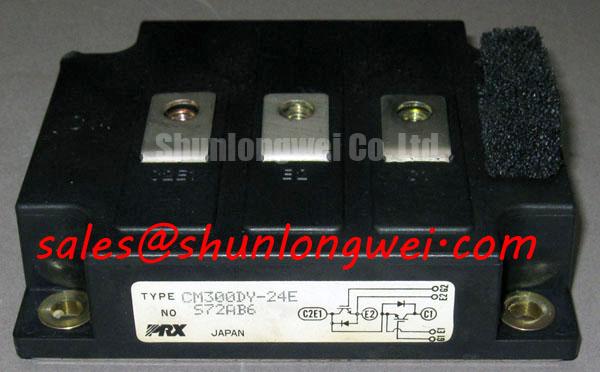
Trace the driver return to the emitter connection identified in the module terminal drawing rather than treating every emitter-connected conductor as an equivalent reference. As a Design Consideration, shared impedance between load current and the gate return can shift the effective gate-emitter voltage during switching. Do not infer a dedicated Kelvin emitter connection from terminal size or position; establish the actual connection from the package diagram and equipment schematic.
For troubleshooting, observe gate-emitter voltage at the module connections with a suitable differential measurement arrangement. Compare the commanded-off interval with the switching activity of the opposing device. A disturbance may involve shared return impedance, capacitive coupling, probe pickup or driver behavior, so changing the gate resistor alone is not a complete diagnosis. Keep measurement loops compact and assess the driver return separately from the main current path.
Driver-board optocouplers or digital isolators also require common-mode transient immunity appropriate to the measured switching environment. This is a board-level Design Consideration, not a CM300DY-24E specification. Evaluate isolation-barrier routing, local supply decoupling and fault-signal behavior together. Terminal clearance and creepage should follow the equipment’s applicable insulation requirements, considering working voltage, pollution conditions and insulating surfaces rather than adopting a distance from the module voltage rating alone.
Bench Tip: Use ESD-controlled handling and discharge the gate through an appropriate protected path before comparing cold-state readings with a reference module.
CM300DY-24E Circuit Protection & Reliability: Assessing Symmetrical Busbar Geometry for High-Current Operation
Compare the outgoing and return current paths before evaluating parallel operation: unequal busbar geometry can produce unequal switching stress even when cold resistance readings appear similar. As a Design Consideration, symmetrical power connections, comparable gate-loop routing and consistent thermal interfaces help reduce differences between branches. Validate the resulting current distribution during both switching transitions and steady operation.
A positive temperature coefficient of collector-emitter saturation voltage can support static current sharing only where the device’s relevant operating curves establish that behavior. It should not be assumed across every current and temperature condition for this model. Dynamic sharing remains sensitive to driver timing, gate impedance and stray inductance, so static conduction measurements cannot substitute for switching observations.
Where the existing high-side driver uses a bootstrap supply, its capacitor assessment should include gate charge at the actual drive conditions, driver quiescent consumption, leakage and the longest interval without recharge. Allowable supply droop must remain consistent with the driver’s undervoltage behavior. This is an Engineering Recommendation for the surrounding circuit; capacitance and recharge requirements belong to the implemented driver topology, not to the module’s headline ratings.
During replacement assessment, compare the CM300HA-24E circuit arrangement, terminal map, mounting geometry and driver requirements separately. A similar model designation does not establish direct interchangeability. For electric material-handling equipment or low-voltage forklift traction repairs, evaluate the original power stage and its losses before considering this voltage class; the 1200 V rating alone does not establish suitability for a battery-powered drive.
Preventing Spurious Faults: Braking-Circuit Thermal Margins for CM300DY-24E
Locate the braking chopper on the equipment schematic before attributing a deceleration fault to the CM300DY-24E. Do not assume that the module incorporates a dedicated braking switch. Establish which semiconductor controls the resistor branch and whether the equipment instead returns energy to a battery or another receptive DC source.
As a Design Consideration, the braking circuit must accommodate the energy delivered during deceleration and the repetition of braking events. Review resistor pulse-energy capability, average dissipation, ventilation and the chopper’s electrical operating limits together. A resistor selected only by its continuous power marking can leave pulse loading unresolved, while a correctly sized resistor cannot compensate for an incorrectly controlled chopper.
When investigating DC-link excursions, correlate bus voltage, brake command and resistor current during a controlled operating sequence. Inspect connections and compare behavior across operating conditions rather than assigning a single cause to an overvoltage alarm. Resistor placement should preserve the equipment’s electrical clearances and avoid heating nearby driver wiring or temperature-sensing components.
For context when comparing switching arrangements, Resonant Topologies in Home Appliances discusses a different converter application; it does not establish braking capability or lifetime for this module. Device-specific technical guidance should remain anchored to Mitsubishi Electric Power Semiconductors & High-Power Modules and the applicable equipment documentation.
Assembly Integrity & Layout Architecture: Applying Junction-to-Case Thermal Models to CM300DY-24E
Use the device-specific transient thermal impedance curve to assess pulsed loading rather than treating case temperature as instantaneous junction temperature. As an Engineering Calculation method, a validated multi-RC network can translate a time-dependent semiconductor loss profile into estimated junction-temperature rise. Its coefficients must come from applicable manufacturer data or a justified fit, not from a visually similar module.
Separate conduction and switching losses using the actual operating conditions, then apply the measured or justified case-temperature boundary. Repeated pulses require thermal history: a pulse beginning before the assembly has cooled starts from an elevated temperature. The estimated peak must be assessed against the manufacturer’s junction-temperature limit, with uncertainty in losses and temperature measurement included in the system review.
Mechanical preparation affects that boundary condition. Inspect the mating surfaces, mounting flatness and thermal-interface coverage, and use the applicable mounting instructions for fastener sequence and torque. Keep terminal loading from distorting the assembly. For insulation testing, use the specified terminal grouping, test conditions and equipment procedure; collector-emitter blocking voltage is not a substitute for a terminal-to-baseplate withstand specification.
In bidirectional DC-DC integration assessments, examine heating during both charging and discharging, including transitions between them. Reducing avoidable temperature swings is a Design Consideration, not a quantified service-life promise. Consult Mitsubishi Electric semiconductor technical resources for applicable device documentation, and retain the loss assumptions, case-temperature measurements and thermal-model inputs with the repair qualification record.