
Content last revised on August 4, 2026
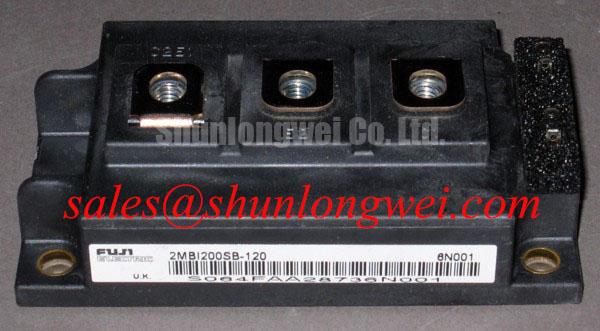
Technical Evaluation of the Fuji Electric 2MBI200SB-120 Dual IGBT Module
This 1200V dual IGBT Module offers optimized thermal dissipation and rugged short-circuit protection for dependable industrial power conversion.
Top specs: 1200V | 200A | Rth(j-c) 0.083°C/W.
Key benefits:
- Low thermal resistance minimizes system cooling requirements.
- 10µs short-circuit withstand time enhances fault survivability.
With a short-circuit withstand time of 10µs, the module allows sufficient time for the protection circuit to trip and prevent thermal runaway. For industrial motor drives prioritizing thermal margins under high load, this 1200V module is the optimal choice.
Application Scenarios & Value
Optimizing Thermal Margin and Reliability in Continuous-Duty Motor Drives
Engineers often face significant thermal stress and power loss challenges when designing high-power industrial converters. In typical three-phase AC inverter designs, continuous high-frequency PWM switching places intense thermal demands on the semiconductor switch. The 2MBI200SB-120 helps mitigate these design bottlenecks through its low junction-to-case thermal resistance (Rth(j-c)) of 0.083 °C/W, which enables highly efficient heat transfer from the silicon junction to the heatsink. This thermal efficiency directly translates to improved power cycling capability, which is critical for long-term system life in heavy industrial applications conforming to the IEC 61800-3 standard. This makes the module a dependable choice for general-purpose Variable Frequency Drives (VFDs) and AC/DC servo drive systems operating between 5 kHz and 15 kHz.
For instance, in a 75kW motor drive application, transient overloads during startup can generate substantial thermal spikes. The module's rated continuous current of 200A, combined with its high peak current capability, ensures adequate headroom during motor acceleration. While this module is ideal for standard 400V AC line systems, designers seeking alternative characteristics for specific system designs may evaluate the related 2MBI200U2F-120, whereas the legacy 2MBI200NB-120 offers a familiar footprint for replacement needs.
Technical Deep Dive
A Closer Look at Silicon-to-Heatsink Heat Transfer and Ruggedness
Understanding the fundamental balance between conduction losses and switching speed is central to integrating the 2MBI200SB-120. The module features a typical collector-emitter saturation voltage (VCE(sat)) of 2.6V at 200A and a junction temperature of 125°C. Think of VCE(sat) as the voltage toll paid by current traversing the semiconductor junction during conduction. A lower toll translates directly to decreased thermal dissipation. For a thorough in-depth analysis of IGBT modules, engineers can consult the in-depth analysis of IGBT modules.
To prevent catastrophic failure, a robust IGBT gate drive design must manage the module's capacitance and internal gate resistance. This module requires precise gate control to optimize turn-on (Eon) and turn-off (Eoff) switching losses. Designers should refer to guidelines for robust IGBT gate drive design to prevent parasitic turn-on and ensure safe shutdown during overcurrent faults. The copper baseplate acts as a thermal highway, smoothing out heat surges from the silicon die, much like a reservoir buffers sudden rainfall to prevent local flooding. This structure ensures that thermal transient spikes do not exceed the absolute maximum junction temperature (Tj) rating of 150°C.
Furthermore, the module's short-circuit withstand time (tsc) of 10µs provides a vital protection window. During a short-circuit event, the current spikes rapidly, and the device must withstand the resulting stress until the controller detects the fault. What is the primary benefit of its planar design? Enhanced short-circuit ruggedness during overcurrent faults. When diagnosing key failure modes, it is clear that a sufficient withstand window is the primary defense against thermal runaway. Engineers looking for methods to evaluate these parameters can read about diagnosing key failure modes.
Key Parameter Overview
Decoding the Specs for Enhanced Thermal Reliability
| Parameter | Specification / Condition | Value | Engineering Interpretation |
|---|---|---|---|
| VCES | Collector-Emitter Voltage | 1200V | Defines the maximum blocking voltage, providing safety margin on 380V–480V AC lines. |
| IC | Continuous DC Collector Current (Tc=80°C) | 200A | Indicates the maximum continuous load current handling capability under standard cooling. |
| VCE(sat) | Saturation Voltage (Tj=125°C, VGE=15V) | 2.6V (Typical) | Determines steady-state conduction losses; lower values reduce heatsink cooling load. |
| Rth(j-c) | Junction-to-Case Thermal Resistance (per IGBT) | 0.083 °C/W | Determines the rate of heat transfer from silicon junction to baseplate, dictating thermal headroom. |
| PD | Maximum Collector Power Dissipation (Tc=25°C) | 1500W | The absolute power limit the silicon can dissipate before thermal damage occurs. |
| Viso | Isolation Voltage (AC, 1 minute) | 2500V | Ensures high-voltage insulation between internal circuitry and ground chassis for safety. |
| tsc | Short-Circuit Withstand Time (VCC=600V, Tj=125°C) | 10µs | The time window available for protection circuits to shut down during terminal faults. |
Download the 2MBI200SB-120 datasheet for detailed specifications and performance curves.
Frequently Asked Questions
Addressing Integration and Fault-Protection Questions
How does the isolation voltage of 2500V protect control electronics?
The 2500V AC isolation rating ensures that high-power transients on the collector-emitter path do not compromise low-voltage gate drive control circuitry. What is the primary benefit of the module's isolated package design? Protection of upstream MCUs and logic circuits from high-voltage feedback.
Why is the 10µs short-circuit withstand time critical for industrial designs?
A short-circuit withstand time of 10µs gives the gate driver's protection logic enough time to detect desaturation. It prevents catastrophic package rupture by shutting down the gate before thermal runaway destroys the silicon dies.
How does the Rth(j-c) value of 0.083 °C/W affect thermal design margins?
A low junction-to-case thermal resistance of 0.083 °C/W permits higher power density. This allows engineers to use smaller heatsinks or reduce forced-air cooling requirements while keeping junction temperatures safely below the 150°C threshold.
Can the 2MBI200SB-120 be operated at switching frequencies above 20 kHz?
While functionally possible, operating above 20 kHz increases switching losses significantly. This shifts the thermal balance and demands substantial derating of the continuous current to prevent the junction temperature from exceeding maximum limits.
What is the engineering significance of the positive temperature coefficient of VCE(sat)?
At elevated temperatures, the saturation voltage increases (from 2.3V typical at 25°C to 2.8V at 125°C). This positive temperature coefficient facilitates safe paralleling because hotter modules naturally carry less current, preventing thermal runaway in parallel setups.
Selecting the appropriate power module requires evaluating conduction losses against thermal dissipation capacities under actual field conditions. Engineering teams should run thermal models using the maximum junction-to-case resistance to ensure sufficient design margins across the full operating range.