


Content last revised on June 1, 2026
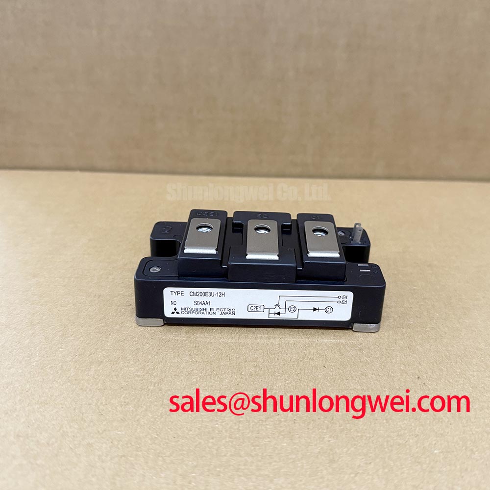
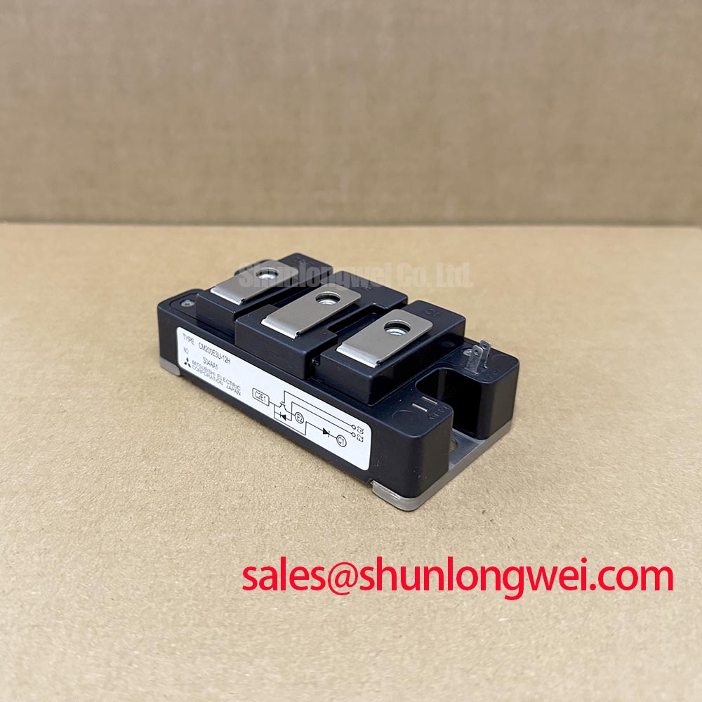
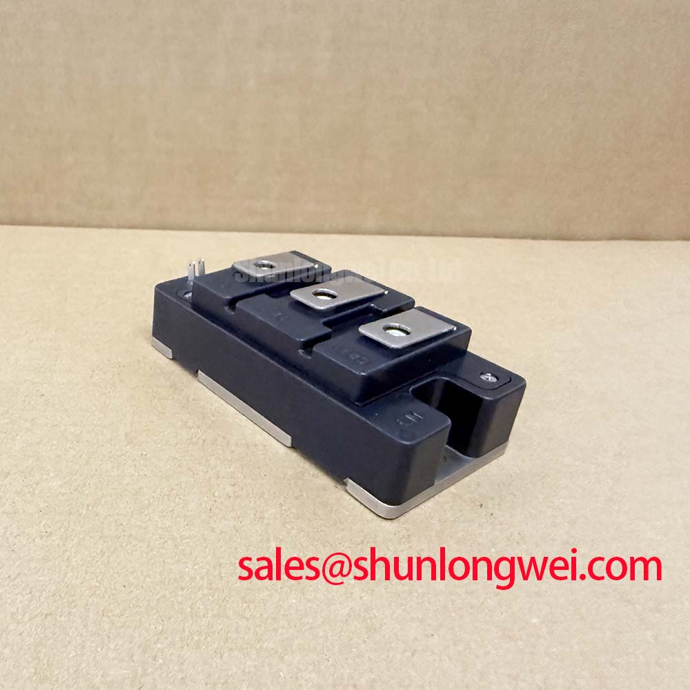
CM200E3U-12H Technical & Application Review: A 600V, 200A Single IGBT Module
An In-Depth Engineering Analysis of the Mitsubishi H-Series IGBT
Engineered for high-frequency power conversion, the Mitsubishi CM200E3U-12H IGBT module minimizes total system losses through an optimized balance of low VCE(sat) and rapid switching characteristics. This device delivers robust performance with key specifications of 600V | 200A | VCE(sat) 2.7V (max), enabling superior thermal efficiency and high-speed operation. By integrating a single IGBT switch with a free-wheeling diode, it directly addresses the engineering need for simplified, high-performance designs in demanding applications like industrial inverters and power supplies. For power systems requiring a lower current rating within the same voltage class, this 200A module offers a significant capacity increase over comparable 150A devices.
Application Scenarios & Value
System-Level Benefits in High-Frequency Power Conversion
The CM200E3U-12H is designed for applications where both conduction and switching losses are critical design constraints. Its performance characteristics make it a strong candidate for high-frequency power conversion systems operating up to 20kHz. What is the primary benefit of its low VCE(sat)? Reduced heat dissipation, which allows for smaller heatsinks and higher power density.
A prime engineering scenario is in the design of a modern Variable Frequency Drive (VFD). In a VFD, the IGBT's ability to switch efficiently directly impacts motor control precision and energy consumption. The CM200E3U-12H's low collector-emitter saturation voltage of 2.7V (max) minimizes power loss during the on-state, which is the dominant state in many motor drive cycles. This is analogous to pushing water through a wider pipe; less energy is wasted as heat. This efficiency gain translates to improved system reliability and a lower total cost of ownership, crucial factors in industrial automation. The module's performance is particularly beneficial for systems employing complex Pulse Width Modulation (PWM) schemes to reduce motor noise and improve torque control.
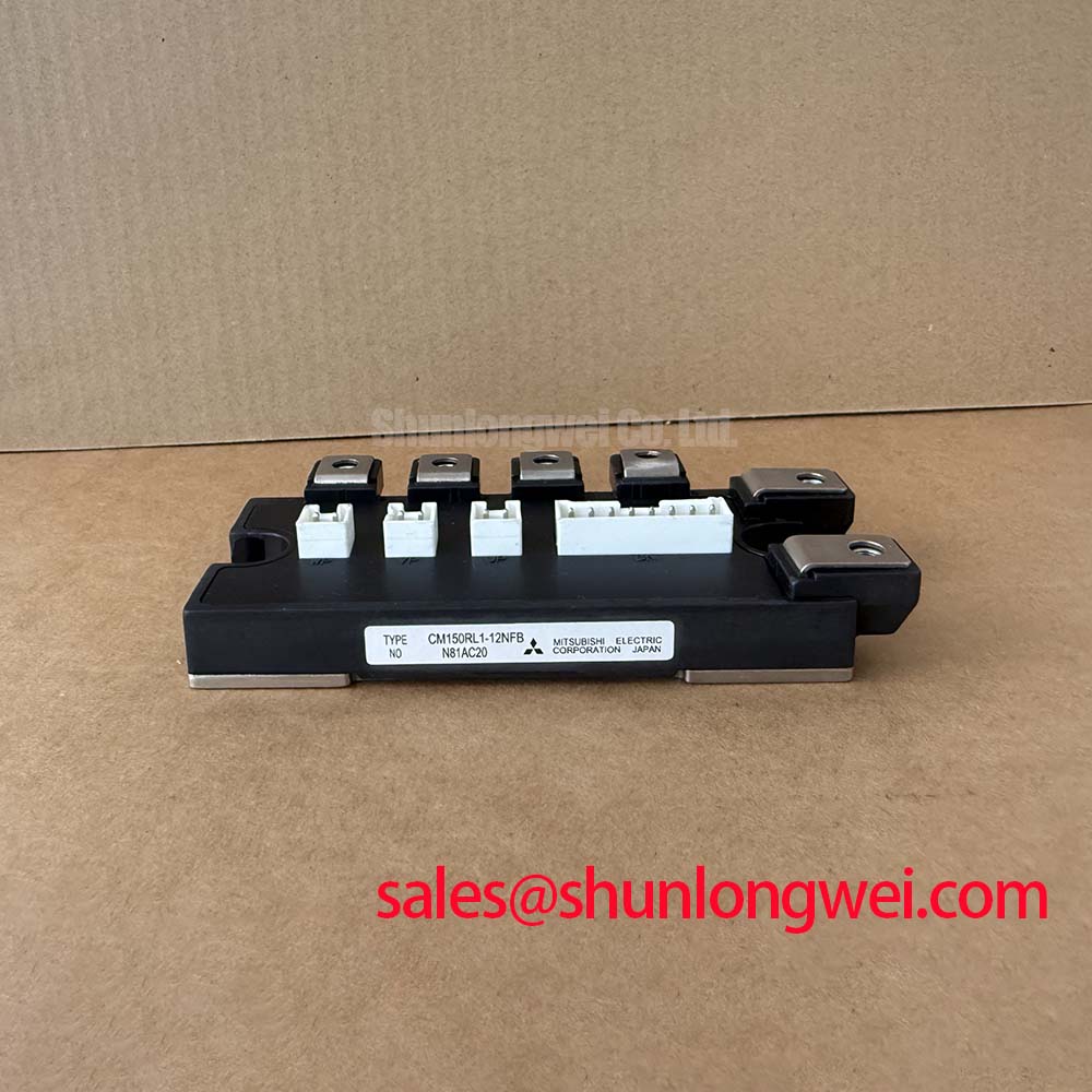
For systems with different current requirements, related components offer alternative ratings. For instance, applications demanding less current handling might evaluate the CM150E3U-12H, which provides a 150A capability in a similar package.
Key Parameter Overview
Functional Performance metrics of the CM200E3U-12H
The technical specifications below are grouped by function to facilitate engineering evaluation. These values, sourced from the official manufacturer's datasheet, are critical for accurate system modeling and thermal design.
| Parameter | Symbol | Condition | Value |
|---|---|---|---|
| Absolute Maximum Ratings (Tj = 25°C) | |||
| Collector-Emitter Voltage | VCES | - | 600V |
| Gate-Emitter Voltage | VGES | - | ±20V |
| Collector Current (DC) | IC | TC = 25°C | 200A |
| Collector Power Dissipation | PC | TC = 25°C | 780W |
| Electrical Characteristics (Tj = 25°C) | |||
| Collector-Emitter Saturation Voltage | VCE(sat) | IC = 200A, VGE = 15V | 2.7V (Max) |
| Gate-Emitter Leakage Current | IGES | VGE = ±20V | 0.5µA (Max) |
| Diode Forward Voltage | VF | IF = 200A | 2.4V (Max) |
| Switching Characteristics (Tj = 125°C) | |||
| Turn-On Time | ton | IC = 200A | 0.50µs (Max) |
| Turn-Off Time | toff | IC = 200A | 0.90µs (Max) |
| Diode Reverse Recovery Time | trr | IF = 200A | 0.25µs (Max) |
| Thermal Characteristics | |||
| Thermal Resistance (Junction to Case, IGBT) | Rth(j-c) | - | 0.15°C/W (Max) |
| Operating Junction Temperature | Tj | - | -40 to +150°C |
Download the CM200E3U-12H datasheet for detailed specifications and performance curves.
Technical Deep Dive
Inside the H-Series: Balancing Conduction and Switching Performance
The CM200E3U-12H is part of Mitsubishi's H-Series, which leverages advanced chip technology to optimize the trade-off between VCE(sat) and switching energy (Eoff). This is a fundamental challenge in IGBT design. A lower VCE(sat) typically implies slower switching speeds and higher turn-off losses. The H-Series addresses this by refining the internal carrier storage and trench gate structures. This allows the CM200E3U-12H to achieve a low on-state voltage without excessively compromising its switching speed, making it suitable for higher frequency operation where both types of losses contribute significantly to the total thermal load. This balance is critical for maximizing the efficiency of power converters and can be explored further in resources like this guide to power semiconductor selection.
Frequently Asked Questions (FAQ)
How does the 2.7V VCE(sat) of the CM200E3U-12H influence thermal design choices?
A lower VCE(sat) directly reduces conduction power loss (P_cond = VCE(sat) * IC). This reduction means less heat is generated for a given current, allowing designers to potentially specify a smaller, more cost-effective heatsink or operate at a higher ambient temperature without exceeding the maximum junction temperature of 150°C. This enhances overall system power density and reliability.
What is the role of the integrated free-wheeling diode (FWD) in this module?
The FWD provides a path for inductive load current to flow when the IGBT is switched off. The co-packaged diode in the CM200E3U-12H is optimized for fast reverse recovery (trr = 0.25µs max), which is crucial for reducing turn-on losses in the IGBT during hard-switching applications like motor drives and SMPS.
Is the CM200E3U-12H suitable for paralleling to achieve higher current?
While this is a single IGBT module, paralleling multiple modules is a common technique. Successful paralleling requires careful consideration of gate drive design, busbar layout symmetry, and the thermal matching of the modules to ensure balanced current sharing. Datasheets often provide guidance on the variation of VCE(sat) with temperature, a key parameter for this analysis. A detailed understanding of these principles is covered in guides on mastering IGBT paralleling.
What does the 'H' in the part number signify?
The 'H' designates this module as part of Mitsubishi's H-Series, which is characterized by its focus on high-speed switching capabilities and low power loss, making it suitable for high-frequency inverter applications.
What are the key considerations for the gate drive circuit for this module?
The gate drive circuit should provide a stable +15V for turn-on and a 0V or slightly negative voltage for a secure turn-off. It must be capable of supplying sufficient peak current to charge and discharge the IGBT's input capacitance quickly to achieve the fast switching times specified in the datasheet. A well-designed Gate Drive is essential for minimizing switching losses and preventing unintended turn-on events.
For engineering teams evaluating this component, detailed electrical and thermal simulations based on the datasheet's performance curves are recommended to validate its suitability for your specific application's operational envelope.