


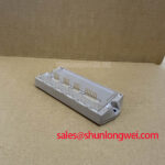
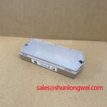
Content last revised on September 19, 2026
7MBP75TEA120 Operational Boundaries: Baseplate Thermal Grease Layer Control Limits
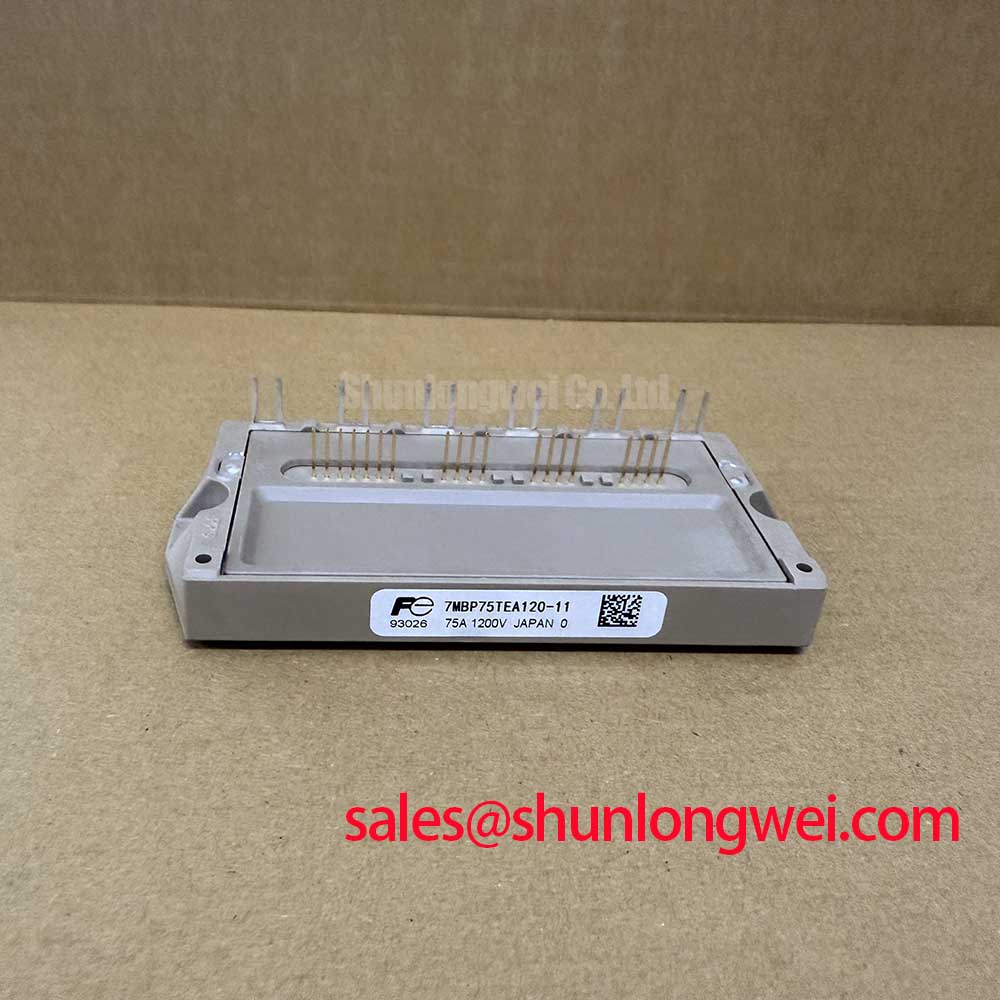
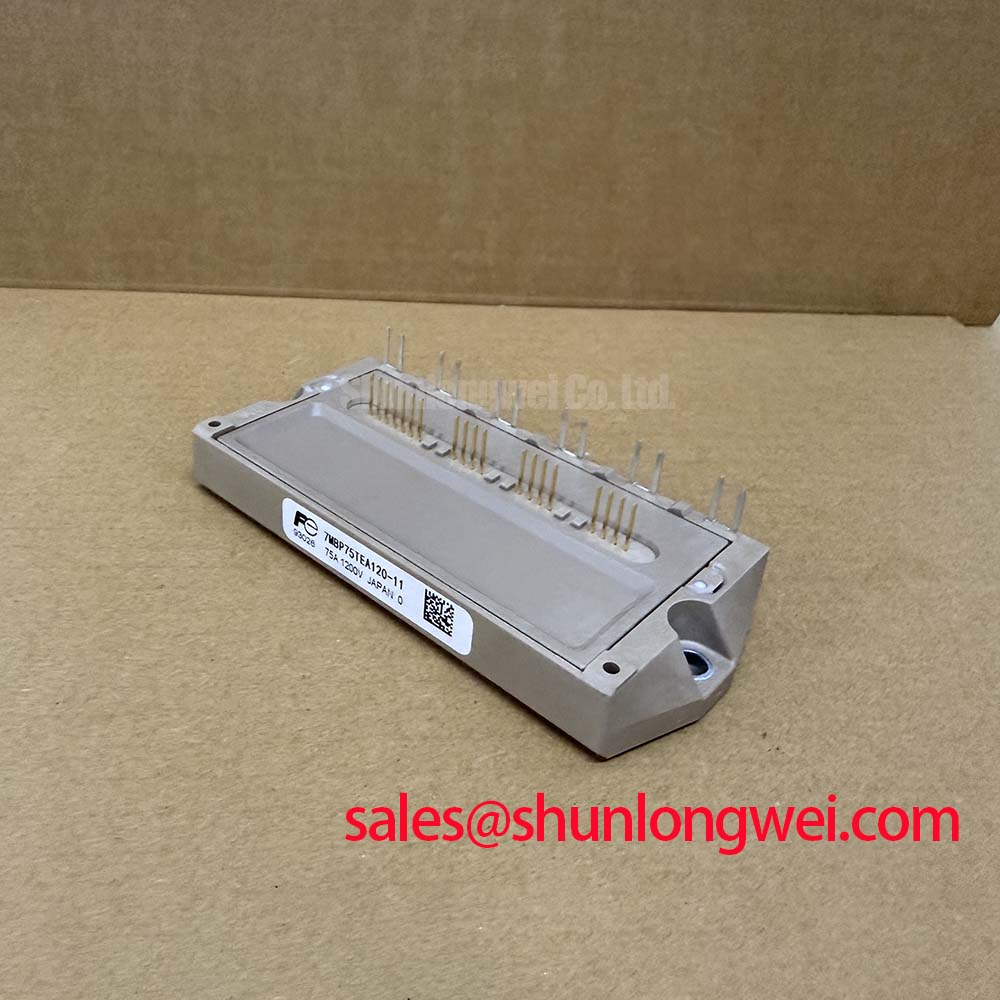
With the inverter deenergized and discharged, first compare the terminal polarity and cold-state diode-mode readings of the installed power stage against a known-good circuit path before fitting the 7MBP75TEA120. This Fuji Electric PIM is rated at VCES 1200V and delivers 75A continuous inverter collector current at TC 80°C, according to the official datasheet specification. Its stated typical collector-emitter saturation voltage is 2.3V at 75A and TJ 25°C. The drive IC supply is specified at 15.0V, with an operating range of 13.5V to 16.5V, while the over-current protection threshold is specified at 112A minimum.
| Official Specification | Rating |
|---|---|
| Collector-emitter voltage | 1200V |
| Continuous inverter collector current | 75A at TC 80°C |
| Collector-emitter saturation voltage | 2.3V typical at 75A, TJ 25°C |
| Over-current protection threshold | 112A minimum |
| Drive IC supply voltage | 15.0V, 13.5V to 16.5V |
| Isolation voltage | AC 2500V for 1 minute |
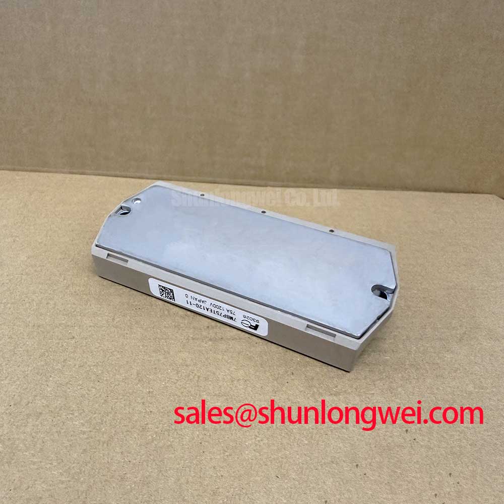
Before tightening the module, inspect the heatsink contact area for raised burrs, trapped debris, corrosion marks, and evidence of previous uneven clamp loading. A continuous, thin thermal interface layer helps transfer heat from the baseplate into the heatsink. A 50 to 100μm grease layer is a general industry design consideration, not an official module requirement. The practical objective is to fill microscopic surface irregularities without creating a thick insulating layer.
Apply the material consistently, position the module without lateral scraping, and tighten mounting screws in a gradual alternating sequence. This helps accommodate normal baseplate and heatsink flatness variation while reducing the chance of localized pressure concentration. After removal from a suspect assembly, uneven grease displacement can be a useful inspection clue, but it does not independently prove a thermal fault. Compare heatsink flatness, fan condition, airflow path, and measured operating temperature before attributing a failure to the interface layer.
The module isolation rating is AC 2500V for 1 minute as an official specification. System integrators should still verify creepage and clearance at the surrounding busbars, terminals, mounting hardware, and enclosure because those external dimensions are determined by the finished equipment layout rather than by the module rating alone.
💡 Bench Tip: Keep ESD controls in place and record cold-state readings before energizing, because comparative measurements are more useful than isolated readings after a fault event.
7MBP75TEA120 Operational Boundaries: Cosmic-Ray Robustness and Voltage-Derating Considerations
The 1200V VCES rating defines the official blocking-voltage boundary, but it does not provide a published altitude derating curve or a quantified cosmic-ray or single-event burnout rate in the supplied product data. Therefore, no FIT value, operating-life prediction, or altitude-specific voltage limit should be assigned to this model without an applicable manufacturer qualification source. This is a design consideration for installations at elevated locations or for equipment exposed to unusual environmental duty.
During commissioning, measure collector-emitter switching peaks at the actual DC-link voltage and load condition. The busbar loop should be kept physically compact to reduce parasitic inductance and associated turn-off overshoot. Snubber film capacitors, where used by the system topology, should be placed to control the local commutation loop rather than treated as a universal retrofit. Final peak-voltage margin must be verified in the completed inverter with appropriate high-voltage probing.
For commercial string inverter and micro-grid energy-storage equipment, the upstream DC-link capacitor bank also affects transient behavior. The energy-storage function of electrolytic capacitors is relevant when assessing bus ripple and switching-loop measurements, although capacitor suitability must be established from the original system documentation.
Benchtop Waveform Tuning: Mitigating Stress via Thermal Capacitance and Heatsink Evaluation on 7MBP75TEA120
Under pulsed overload testing, do not infer junction condition from heatsink temperature alone. The thermal response from junction to case and from case to heatsink occurs over different time intervals, so a stable heatsink measurement can coexist with short-duration semiconductor stress. As an engineering recommendation, correlate current waveform, pulse duration, case temperature trend, and switching behavior during controlled testing rather than relying on a single thermal indicator.
The specified typical 2.3V VCE(sat) provides one reference point for conduction-loss assessment at the stated 75A and 25°C junction temperature condition. Real operating loss changes with current, temperature, switching conditions, and modulation pattern. Engineers evaluating RMS current should use the system waveform rather than its peak value alone; the basic relationship between RMS current and resistive heating is explained in this reference on RMS current calculations.
Check that the drive supply arriving at the module remains inside the official 13.5V to 16.5V range during switching activity. If a waveform shows excessive ringing or an unexpected protection response, examine the gate-drive supply stability, isolation barrier behavior, local decoupling, and power-loop layout before changing component values. For background on controlled turn-off drive evaluation, see Evolution of Negative Off-Bias Gate Drive Circuits.
Field Diagnostics & Commissioning: Multi-Module Parallel Current Sharing in 7MBP75TEA120 Topologies
Parallel power-module assemblies require both static and dynamic comparison. The positive temperature tendency of VCE(sat) can support steady-state current sharing in appropriate IGBT operating regions, but it does not guarantee equal current division in a finished converter. Differences in heatsink contact, busbar resistance, gate-loop routing, driver propagation delay, and protection timing can shift the sharing result.
When evaluating parallel positions, use matched current probes and compare phase-current waveform shape, switching edge timing, and case-temperature trend under the same operating point. Route corresponding gate-drive paths symmetrically and verify that each module sees the correct drive supply. The internal over-current protection threshold of 112A minimum is an official module parameter, yet external control and fault-management behavior remain system-dependent.
For a comparison candidate with the same nominal voltage and current class, engineers may review the documented characteristics of BSM75GD120DLC against the original circuit requirements. In systems where an associated rectifier or complementary power stage is being assessed, BSM75GB120DN2 can be reviewed as a separate topology component. Compatibility should be confirmed from the original schematic, terminal arrangement, protection architecture, and measured switching behavior.