


Content last revised on September 18, 2026
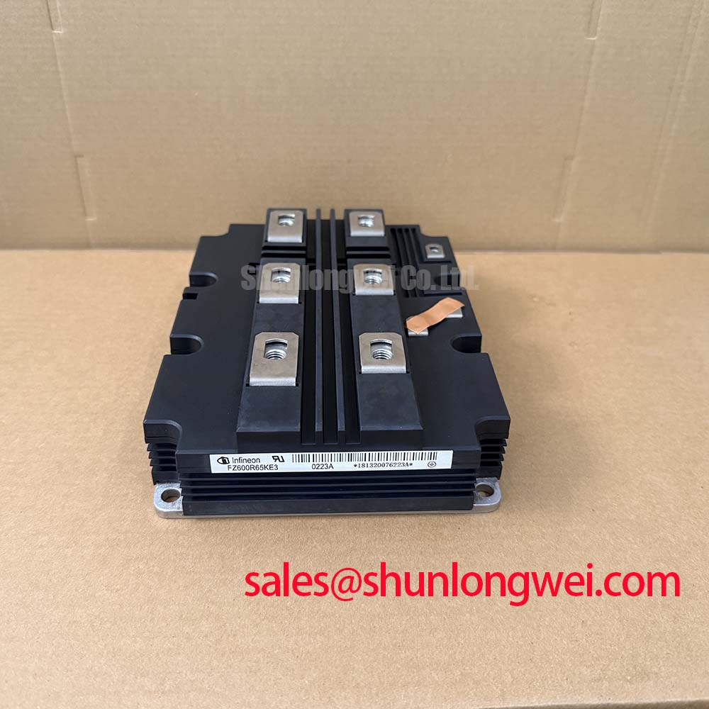
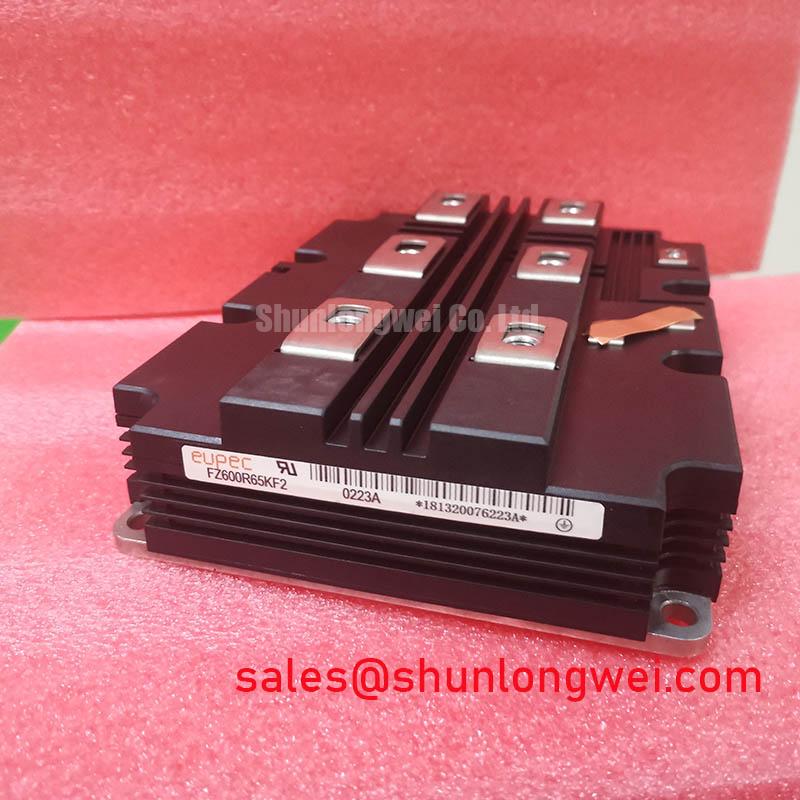
With the converter isolated and discharged, first verify that the installed nameplate calls for FZ600R65KF2 and that the listed electrical ratings are 6500.0V and 600.0A before assessing a replacement or investigating a power-stage fault. This Infineon device is supplied in a Module package. These are Official Specification values and define the starting point for compatibility review; they do not establish the permissible DC bus, switching conditions, cooling capacity, or gate-drive settings of a particular converter.
| Parameter | Value | Specification Status |
|---|---|---|
| Product model | FZ600R65KF2 | Official Specification |
| Manufacturer | Infineon | Official Specification |
| Voltage rating | 6500.0V | Official Specification |
| Current rating | 600.0A | Official Specification |
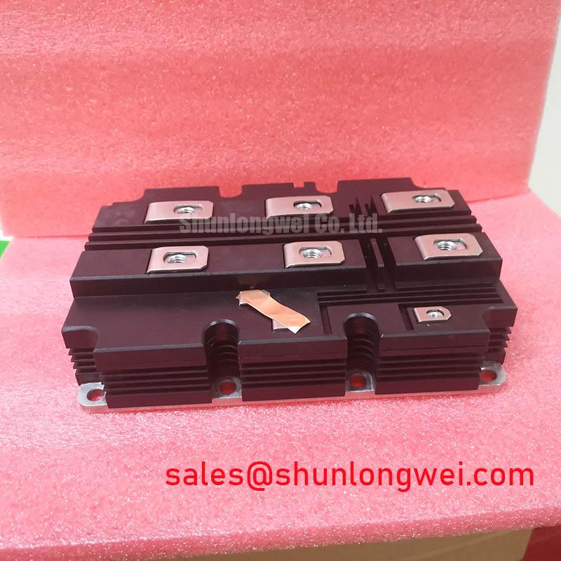
| Package | Module | Official Specification |
For product-family context, consult the Infineon IGBT Modules and Discretes portfolio and the manufacturer’s IGBT Modules overview. The original equipment documentation remains the authority for terminal arrangement, driver interface, protection thresholds, thermal stackup, and commissioning limits.
Transient Dynamics & Electrical Design: Optimizing Heatsink Contact Pressure on FZ600R65KF2
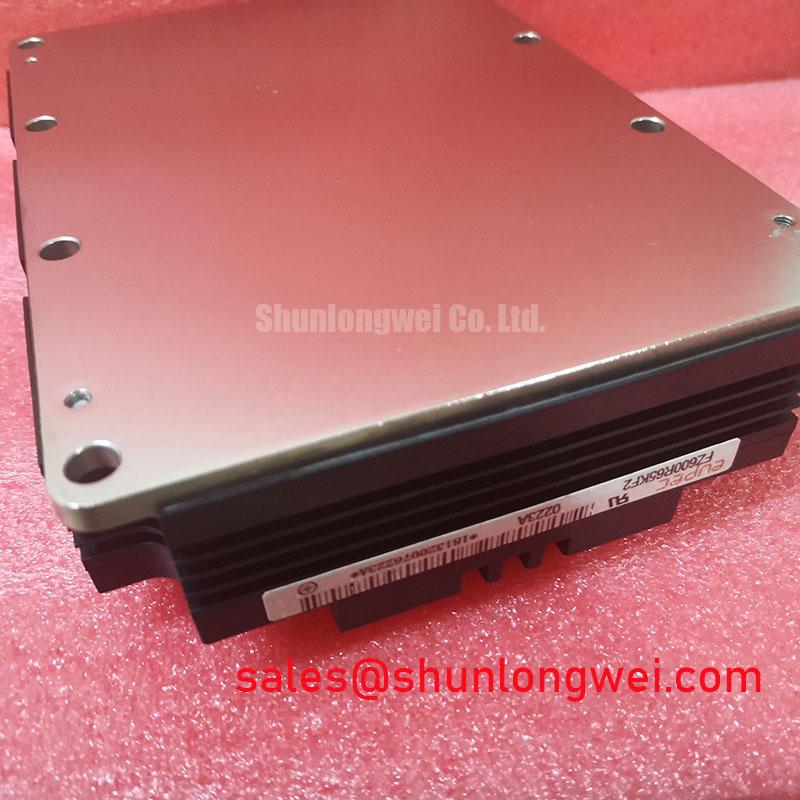
Before reconnecting DC buswork, inspect the mating heatsink face for raised burrs, embedded debris, corrosion products, and local damage around mounting locations. A power module can show acceptable static semiconductor readings while uneven mechanical contact raises operating junction temperature during loaded converter operation. On large converter assemblies, compare the removed module’s contact pattern with the replacement installation area and clean the surface using the maintenance procedure approved for the equipment.
Thermal interface material must form a continuous interface rather than a collection of thick ridges. A 50 to 100 µm thermal interface layer is a General Industry Design Consideration when the selected material and the equipment manufacturer’s mounting process support that range. Its purpose is to fill microscopic surface variation without becoming the dominant thermal resistance. The system integrator should use the original converter documentation to determine the approved material, application pattern, and quantity.
Baseplate flatness, heatsink flatness, and mounting sequence interact. Where service access permits, bring screws down in a balanced sequence from the interior mounting positions toward the exterior, then perform the final torque sequence required by the converter manufacturer. This helps distribute contact pressure and can reduce local lift caused by surface curvature. Do not interpret a general mounting practice as an official FZ600R65KF2 torque specification.
Electrical clearance around exposed bus connections also deserves inspection after mechanical work. Keep conductive tools, loose washers, displaced sensing wires, and thermal compound away from live connection areas. Where a converter uses disc springs or other clamping hardware, retain the original stack order and confirm that each spring remains seated. The clamping arrangement belongs to the converter mechanical design and should be verified against its service documentation.
Maintenance Note: Monitor heatsink contact temperature trends and inspect the airflow path for dust accumulation before a recurring temperature alarm becomes a converter shutdown.
FZ600R65KF2 Thermal-Electrical Optimization: Calculating Failures-in-Time Rates in High Practical Tuning
No Failure in Time value, Single Event Burnout rate, altitude derating curve, or service-life figure should be assigned to FZ600R65KF2 without a manufacturer specification or a cited system-level qualification study. Terrestrial neutron exposure, operating altitude, DC bus stress, semiconductor temperature, switching waveform, and protective response are system-dependent variables. A repair decision should therefore separate the official 6500.0V module rating from the converter’s measured operating stress.
For installations operating above 2000 m, altitude and environmental qualification should be reviewed against the original equipment requirements. This is a Design Consideration rather than an asserted device rating. Engineers evaluating a multi-megawatt offshore or onshore wind turbine full-scale converter should capture DC-link voltage, switching waveforms, cooling conditions, and fault records under controlled procedures before changing the operating envelope.
Turn-off overshoot is influenced by the inductance of the current commutation loop and the rate at which current changes. A laminated busbar layout, short return paths, secure bus joints, and film capacitors placed according to the converter design can help limit parasitic inductance and associated transient voltage. The required arrangement and its verified peak-voltage margin must be determined through system switching tests, with measured results compared against the DC-link voltage and applicable equipment limits.
A MOV network may be part of an equipment-level overvoltage strategy, but its presence does not remove the need to inspect the DC-link capacitor network, busbar fasteners, snubber connections, and fault-event logs. MOV selection, energy capability, coordination with snubber capacitors, and protective-device behavior are Design Considerations set by the converter architecture. For a broader technical reference during waveform review, see The Ultimate IGBT Knowledge Base.
Field Diagnostics & Commissioning: Thermal Feedback in FZ600R65KF2 Topologies
With power removed and discharge verified, compare the phase-leg assembly against a known-good section where the equipment design permits. Check terminal hardware, gate-drive plugs, fiber or control connectors, current-sensor routing, cooling passages, and insulation barriers. A visual inspection alone cannot prove dynamic health, but it can identify disturbed interfaces that deserve correction before controlled energization.
In parallel semiconductor arrangements, the positive temperature coefficient of VCE(sat) is commonly considered during steady-state current-sharing analysis. It does not guarantee equal current sharing during switching. Dynamic balance depends on matched gate-loop routing, driver behavior, busbar geometry, device condition, and the timing of the complete protection system. Engineers should compare relevant waveforms between parallel positions using appropriate isolated measurement methods and the converter’s approved test procedure.
During commissioning, a difference in temperature rise or switching signature may indicate several possible issues, including unequal mechanical contact, altered driver impedance, inconsistent sensing, or a change elsewhere in the power loop. Avoid assigning a single cause from one symptom. Record conditions, verify measurements against a known-good signal path, and establish whether the behavior follows the module position, the driver channel, or the surrounding assembly.
Where the repair scope includes a separate input or auxiliary power stage, FZ800R12KS4_B2 can be reviewed as a distinct IGBT module reference. Its voltage and current ratings must be assessed independently; it is not an assumed substitute for FZ600R65KF2. A different voltage class and current class require a new topology, interface, protection, and thermal compatibility review.
Field Diagnostics & Commissioning: Dynamic Gate Impedance Control for Robust FZ600R65KF2 Topologies
Gate-loop inspection should begin at the installed driver board and continue through every connector, resistor location, return path, shield termination, and module control terminal defined by the original design. High dv/dt conditions can couple disturbance into a gate circuit and can contribute to unwanted switching if the return path or driver clamp function is compromised. A dedicated low-impedance active Miller clamp is a Design Consideration when the original driver architecture uses one; verify its operation within the equipment documentation and approved test conditions.
Negative gate bias is also a system-level gate-drive decision. Its required value depends on driver capability, insulation coordination, switching conditions, and the module manufacturer’s relevant gate limits. The system integrator should not apply a generic bias value to FZ600R65KF2. Instead, inspect the original driver supply rails and command waveform, then validate gate behavior during controlled switching tests.
For repair planning, FZ600R65KF2 should be compared only against candidates whose official voltage class, current capability, package interface, topology, cooling arrangement, and driver requirements have all been verified. The FZ3600R12HP4 is available for neutral cross-model evaluation, but its different published ratings require a complete engineering review rather than a direct replacement assumption.