


Content last revised on July 4, 2026
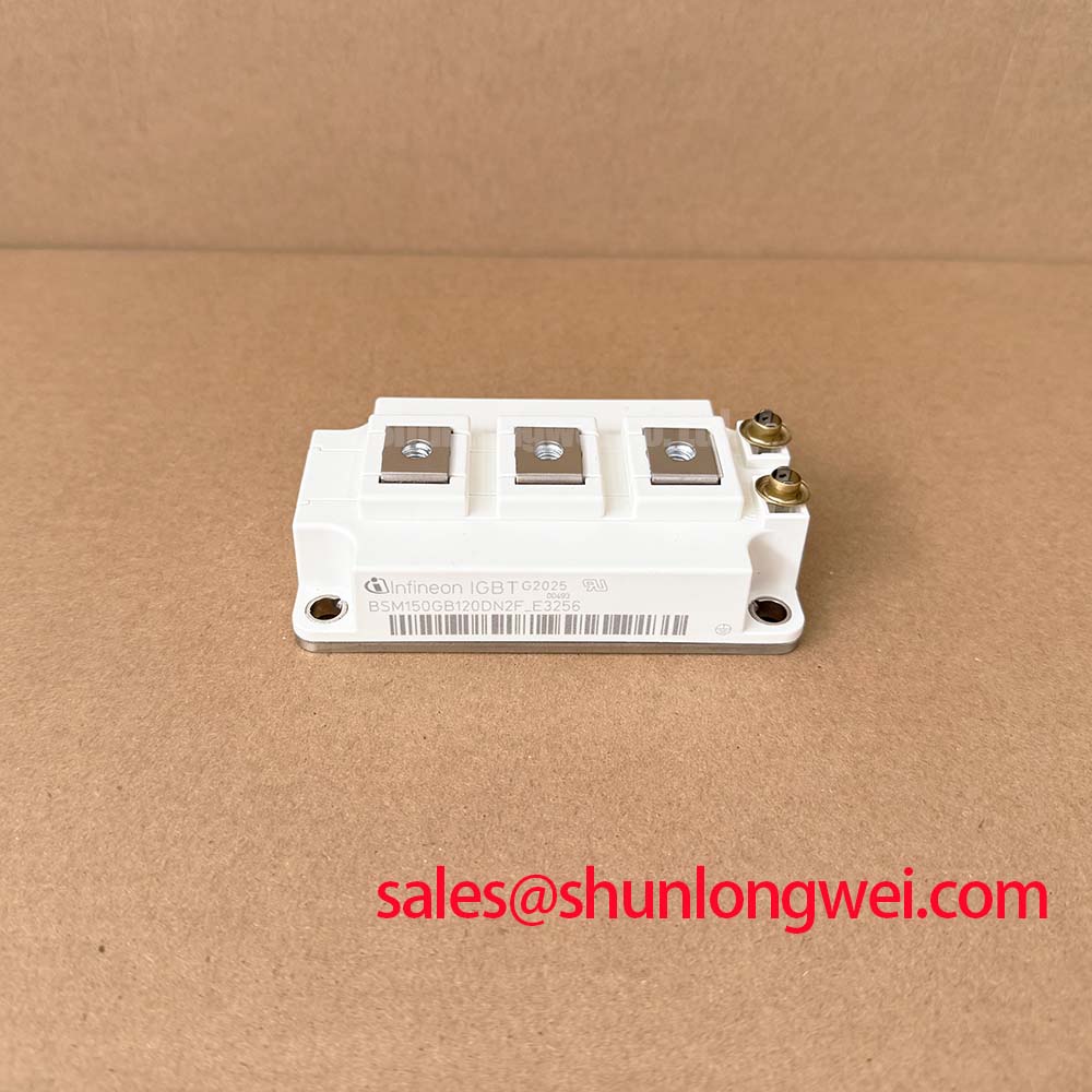
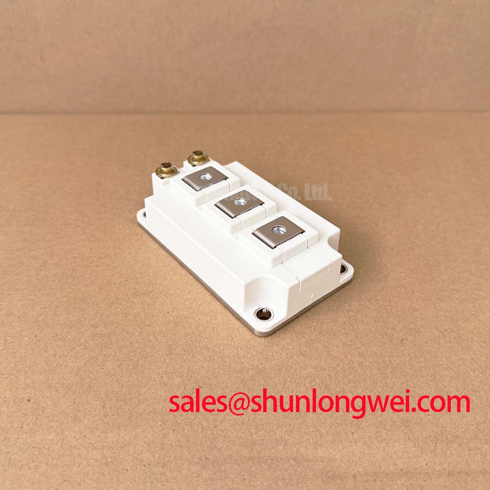
Infineon BSM150GB120DN2F_E3256 1200V 150A Dual IGBT Module
The Infineon BSM150GB120DN2F_E3256 provides efficient, fast-switching power control in a compact half-bridge configuration, optimizing thermal dissipation in industrial converter stages.
Top Specs: 1200V | 150A | 1250W power dissipation per switch.
- Low thermal resistance.
- Fast freewheeling diode protection.
Why does this module integrate fast freewheeling diodes? To suppress high-voltage inductive transients during high-frequency switching.
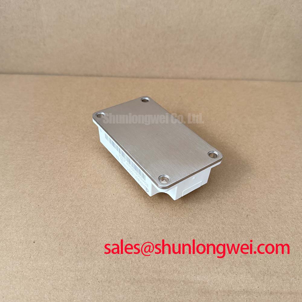
What is the benefit of the insulated metal base plate? It minimizes thermal resistance, preventing localized hot spots under load.
For 400V AC industrial motor drives requiring optimized switching speed and thermal overhead, the 1200V BSM150GB120DN2F_E3256 is the ideal power stage.
Key Parameter Overview
Decoding the Specs for Enhanced Thermal Reliability
The following parameter table highlights the main technical boundaries and characteristics of the Infineon BSM150GB120DN2F_E3256.
| Parameter | Symbol | Standard Rating | Engineering Significance |
|---|---|---|---|
| Collector-Emitter Voltage | VCES | 1200 V | Maximum blocking voltage capability |
| Continuous Collector Current (TC = 80°C) | IC | 150 A | Continuous output rating under operational load |
| Continuous Collector Current (TC = 25°C) | IC | 210 A | Peak capability at cold start or startup cycle |
| Collector-Emitter Saturation Voltage (Tj = 25°C) | VCE(sat) | 2.5 V (typ) / 3.0 V (max) | Direct indicator of conduction losses |
| Max. Power Dissipation (per IGBT, TC = 25°C) | Ptot | 1250 W | Maximum allowable dissipation limit |
| Thermal Resistance (Junction-to-Case) | Rth(j-c) | ≤ 0.1 K/W | Thermal heat transfer efficiency from silicon |
| Insulation Test Voltage (t = 1 min) | VISOL | 2500 Vac | Safety isolation between electrical path and baseplate |
Download the BSM150GB120DN2F_E3256 datasheet for detailed specifications and performance curves.
Application Scenarios & Value
Achieving System-Level Benefits in Industrial Power Inverters
Engineers face critical thermal limits during heavy startup currents in conveyor systems and factory motor controllers. When a high-inertia motor starts, a massive load surge occurs, threatening to drive the silicon junction temperature past safe thresholds. The Infineon BSM150GB120DN2F_E3256 mitigates this risk by providing a temporary current handling margin up to 210A when the case temperature is 25°C. Combined with its low junction-to-case thermal resistance (Rth(j-c) ≤ 0.1 K/W), thermal energy is rapidly channeled away, preventing catastrophic thermal runaway. The integrated fast freewheeling diodes clamp inductive reverse-voltage spikes, ensuring safety within the SOA (Safe Operating Area) during fast turn-off sequences.
This dual-channel half-bridge module is commonly deployed in modular uninterruptible power supplies (UPS), solar inverters, and medium-power industrial drives. While this 150A module fits standard systems, for designs requiring higher continuous current outputs, the related BSM200GB120DN2 offers a nominal rating of 200A, while the three-phase BSM150GT120DN2 can simplify inverter layouts.
Technical & Design Deep Dive
Analyzing the Non-Punch-Through Design and Thermal Highway
The core technology behind the Infineon BSM150GB120DN2F_E3256 relies on a Non-Punch-Through (NPT) silicon structure. NPT chips feature a positive temperature coefficient for VCE(sat), making them highly stable when operated in parallel. Conduction losses are kept low with a VCE(sat) of 2.5V, while the fast switching configuration (indicated by the "F" suffix) ensures minimal switching losses. Designers should refer to the definitive guide to IGBT selection to balance these switching speed improvements against electromagnetic interference (EMI) requirements.
Thermal management dictates the ultimate limit of any high-power converter. The insulated metal base plate in this package acts like a multi-lane highway, allowing heat to flow freely to the heatsink and preventing the thermal gridlock common in smaller packages. This packaging performance is detailed in our in-depth analysis of IGBT modules. To maximize reliability, designers must utilize a robust IGBT gate drive design to prevent parasitic turn-on and voltage overshoot.
By prioritizing long-term circuit durability and low thermal fatigue, this module series provides a solid architectural choice for industrial systems transitioning to high-efficiency, multi-phase converter designs.
Frequently Asked Questions
Engineering Queries and Operational Integration Clarifications
What is the primary benefit of the "F" suffix on the BSM150GB120DN2F_E3256?
The "F" suffix indicates that this module features optimized fast-switching characteristics alongside integrated fast-recovery freewheeling diodes. This reduces switching losses in high-frequency applications like switch-mode power supplies.
How does the Rth(j-c) rating of ≤0.1 K/W impact system heatsink design?
The low thermal resistance indicates highly efficient heat transfer from the IGBT junction to the package case. This allows system engineers to specify smaller, lighter heatsinks or run the module at higher average power levels without exceeding the maximum operating junction temperature of 150°C.
What does the suffix "_E3256" denote on this module?
The "_E3256" suffix is a manufacturer-specific code representing a specialized build option. While the core electrical and thermal ratings (1200V, 150A) remain identical to the standard BSM150GB120DN2F, it typically indicates minor mechanical modifications, optimized terminal platings, or factory-specific screening options.
Can the BSM150GB120DN2F_E3256 be paralleled for higher current requirements?
Yes. Because it uses NPT technology, the collector-emitter saturation voltage has a positive temperature coefficient at higher currents. This natural physical property ensures equal current sharing between paralleled modules, preventing thermal runaway in one dominant switch.