

Content last revised on October 6, 2026
CM10MD1-24H Circuit Protection and Reliability: Checking Motor-Lead Voltage Stress
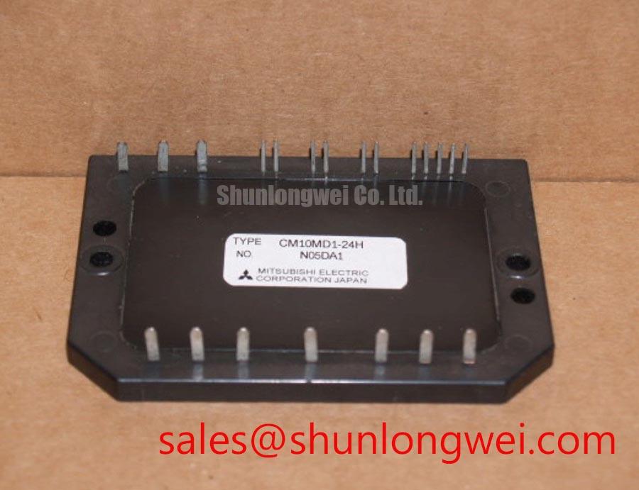
With the drive isolated and its DC link discharged, check the CM10MD1-24H module marking against the maintenance record before disturbing the motor or gate connections. The supplied product specifications identify this Mitsubishi Electric IGBT module as rated at 1200 V and 10 A (Official Specifications), with a module package. Those ratings establish an initial identity check; they do not, by themselves, confirm the terminal arrangement, gate-drive requirements, mounting dimensions, or suitability for a particular servo amplifier.
When assessing this module in a multi-axis CNC or robotics servo drive, start at the motor terminals as well as the power stage. Long motor leads can produce reflected-wave voltage peaks when cable and motor impedances are mismatched. This is a system-level Design Consideration, not a stated voltage capability of the CM10MD1-24H. A drive that appears stable at its DC link can therefore still warrant a motor-terminal waveform check, particularly after a cable-length, routing, or motor change.
Use an appropriately rated differential measurement setup and compare the motor-terminal waveform with the drive-output waveform under the operating conditions that produce concern. Record the cable configuration and switching settings so that a later maintenance team can repeat the test. If peaks or ringing require mitigation, the system engineer should evaluate an output filter or choke against the drive manufacturer’s instructions, motor insulation requirements, and measured waveforms. Filter selection cannot be established from the module’s 1200 V and 10 A ratings alone.
For bearing-current complaints, inspect the motor grounding path, cable shield termination, and any installed common-mode mitigation before assigning the fault to the IGBT module. Keep power conductors and sensitive feedback wiring separated according to the equipment design, and preserve the original enclosure clearances during repair. Noise observed on an encoder channel may have several causes; a comparison with a known-good axis is more useful than treating one waveform feature as a diagnosis.
Assembly Integrity and Layout Architecture for CM10MD1-24H
Before transferring a module into an existing assembly, compare its mechanical outline, terminal positions, connection diagram, and mounting interface with the original equipment documentation. The package description Module (Official Specification) is not a substitute for a dimensional drawing. Confirming these details early prevents a nominal voltage-and-current match from being mistaken for a physical or electrical fit.
Where a power stage uses parallel switching paths, symmetrical busbar geometry and comparable gate-loop wiring are Design Considerations for reducing differences in stray inductance and switching behavior. Do not assume that the CM10MD1-24H has a specified positive temperature coefficient suitable for static current sharing; that claim requires the applicable device curves and operating conditions. The same caution applies to any proposed parallel-module arrangement. Current balance should be checked in the actual assembly rather than inferred from the model designation.
Gate-drive sourcing and sinking capability should be assessed from the verified module documentation and the installed driver design. If external gate resistance is adjustable, an Engineering Recommendation is to tune it while observing gate and collector waveforms: excessive ringing and excessive switching loss pull the decision in different directions. Keep the measurement reference close to the intended gate-return point and compare results under representative load. A resistor value copied from another drive does not establish acceptable behavior here.
For a parameter comparison, CM300DXDX1-24A is a separate Mitsubishi Electric module to evaluate on its own datasheet and mechanical drawing. Its different model designation is not evidence of interchangeability with CM10MD1-24H.
Field Diagnostics and Commissioning: Gate Impedance and Unintended Turn-On
After wiring work, inspect the gate connections against the equipment schematic before applying drive power. Check connector seating, conductor routing, and the condition of the gate-return path. With the drive isolated, compare appropriate cold-state measurements with the service documentation and, if available, a known-good axis. An unexpected reading warrants investigation, but it should not be assigned to a single failure mechanism without further checks.
During controlled commissioning, high collector-voltage slew rate can couple into a gate circuit and contribute to unintended turn-on. Active Miller clamping, negative gate bias, and low-impedance turn-off paths are possible system-level Design Considerations, not confirmed built-in features or prescribed settings for this module. Whether any of them is appropriate depends on the verified gate limits, driver arrangement, isolation scheme, and switching measurements. Probe the gate signal with equipment suited to the circuit’s potential, then check turn-off behavior alongside collector-voltage overshoot and driver fault indications.
Thermal and electrical symptoms should be recorded together. An axis that trips under acceleration may call for checks of load current, cooling airflow, gate-drive behavior, and DC-link conditions; the trip alone does not identify the module as the cause. The Field Engineer’s Handbook provides broader testing and failure-analysis context for documenting those comparisons. If the same machine includes an industrial HMI, its display backlight is a separate subsystem; a blank screen should not be treated as direct evidence of an IGBT fault.
Benchtop Waveform Tuning and Baseplate Thermal Interface Control
Inspect the heatsink contact surface before mounting the CM10MD1-24H. Remove old thermal-interface material using a method compatible with the equipment, then check for contamination, damaged threads, and contact-surface distortion. Apply the specified thermal material in accordance with the original assembly instructions. A visibly uneven layer or trapped debris can compromise contact, but an exact grease thickness or screw torque should not be presented as a module specification without the applicable mounting document.
Seat the module evenly and follow the equipment’s specified fastener sequence and torque procedure. After reassembly, verify that cables have not been pulled against terminals and that cooling passages remain clear. During the first controlled run, compare heatsink temperature behavior, load current, and switching waveforms with the maintenance baseline. Temperature rise should be interpreted in light of ambient conditions and duty cycle rather than from one isolated reading.
⚠️ Maintenance Note: Isolate and discharge the drive before retightening terminals, and check the heatsink airflow during scheduled inspections.
For recurring thermal concerns, document fan operation, dust buildup, thermal-interface condition, and terminal condition before changing gate settings. This separates a cooling-path problem from a switching problem and leaves the next maintenance shift with measurements it can reproduce.