

Content last revised on October 23, 2026
CR6L-100-UL Product Identity and Replacement Checks
- Verify the marked 600.0 V voltage rating and 100.0 A current rating against the drive protection scheme, including the applicable AC or DC voltage rating.
- Inspect the fuse body, terminals, mounting hardware, and contact surfaces for heat damage, looseness, or contamination.
- Confirm that the replacement position is a semiconductor protection location rather than a conventional motor branch fuse position.
- Isolate all power sources and verify that the DC link is discharged before removing or inserting the fuse.
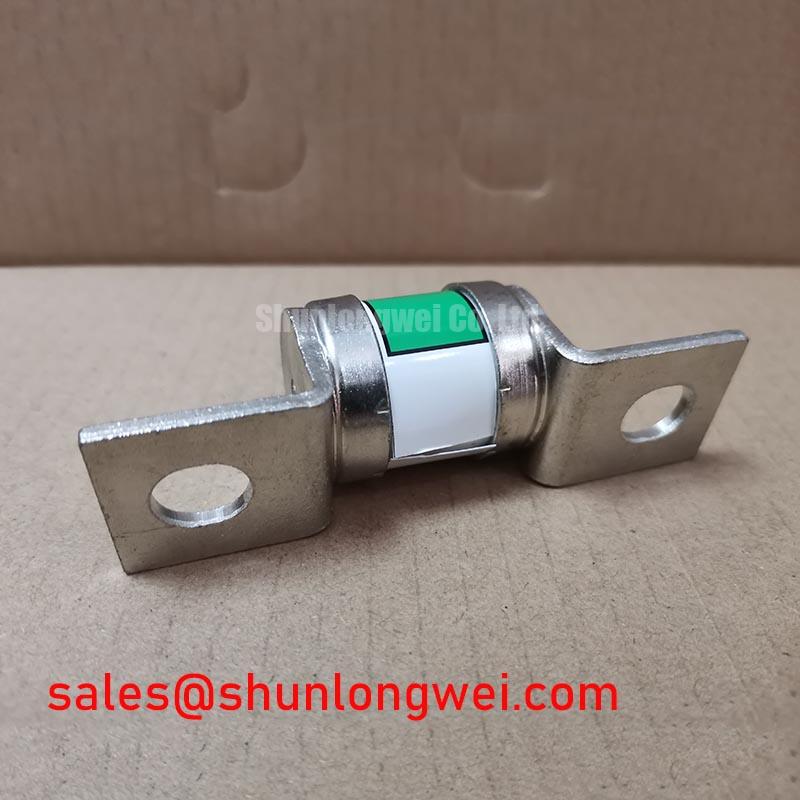
The CR6L-100-UL is a Fuji Electric High Speed Super Rapid Fuse with a listed 600.0 V rated voltage and 100.0 A rated current. The voltage rating must be checked against the manufacturer’s applicable AC or DC conditions; a 600 V AC rating does not establish a 600 V DC interrupting capability. The fuse is evaluated by its interrupting behaviour, semiconductor protection suitability, thermal installation conditions, and coordination with the converter protection network rather than by gate-drive characteristics.
CR6L-100-UL Operational Boundaries: Evaluating Dynamic Braking Chopper Operation Limits
In a heavy-duty variable frequency AC motor drive, a suitably selected and coordinated fuse can protect the semiconductor power path when a braking chopper fault, DC-link short circuit, or severe switching failure creates a high-energy fault current. Use of the CR6L-100-UL in a DC-link or braking circuit requires confirmation of its applicable DC voltage and interrupting ratings. It does not regulate braking energy and should not be treated as the element that absorbs normal motor deceleration energy. The braking IGBT and ballast resistor must be assessed separately for their switching duty, pulse energy, thermal recovery, and DC-link operating conditions.
During commissioning, examine the braking resistor circuit for signs of repeated overload, then compare the measured DC-link behaviour with the drive manufacturer’s protection thresholds. A fuse replacement should preserve the intended semiconductor protection coordination. Its current rating alone does not establish suitability for a particular pulse profile, because clearing performance depends on the fault waveform, available source energy, circuit impedance, and the protected device’s withstand capability.
For layouts containing a MOV network, place the surge suppression path so that its connection does not introduce unnecessary loop inductance around the switching cell. This is a Design Consideration, not a CR6L-100-UL datasheet specification. Engineers evaluating a related converter topology may also review the 6MBP100RTB060 product page as a separate component reference, without assuming interchangeability.
CR6L-100-UL Circuit Protection & Reliability: Fuse Mounting and Connections
The CR6L-100-UL is a fuse and has no gate, emitter, or Kelvin emitter terminal. A Kelvin emitter wiring concern belongs to the IGBT or power module installed in the same converter, while the fuse must be mounted with the correct mechanical contact pressure and low-resistance current path specified by the equipment design.
Do not transfer IGBT installation practices, such as thermal interface material thickness or cross-pattern semiconductor module torque, to this fuse unless the original holder or equipment documentation explicitly requires them. The practical inspection is different: clean mating surfaces, confirm the holder is mechanically secure, check that the fuse is not forced into alignment by busbar stress, and inspect the terminal area after a controlled operating test for abnormal heating.
Where a front-end rectifier and inverter share a protection architecture, the 6MBP100KB060 may be reviewed as a separate system-level reference. Its electrical role must not be confused with the CR6L-100-UL fuse. Engineers should also verify the fuse’s time-current and I²t coordination from the applicable Fuji Electric documentation before approving a replacement.
Benchtop Testing: Evaluating Thermal and Fault-Circuit Stress on CR6L-100-UL
Bench testing should focus on the fuse’s surrounding fault circuit rather than attempting to derive a junction-to-case thermal model for an unspecified internal construction. Record the DC-link voltage, braking command, resistor current, and switching fault response with properly rated probes. A thermal scan of the fuse body and its holder can reveal uneven contact heating, while a controlled current test can help distinguish installation resistance from a wider converter fault.
For repeated braking events, the resistor and braking IGBT require their own transient thermal analysis using the manufacturer’s thermal impedance data. The CR6L-100-UL should then be checked for coordination with that protection chain. The listed 600.0 V and 100.0 A ratings do not by themselves provide a permissible overload pulse duration or an I²t value.
The Peak Efficiency in Solar and Energy Storage reference can support broader topology review, but it should not be treated as a substitute for the fuse manufacturer’s application data. Bench Diagnostic: Never use a temporary wire link in place of the fuse during a live high-energy DC-link test.
Preventing Spurious Faults: Transmission-Line Stress and CR6L-100-UL Protection Coordination
Long motor leads can create reflected-wave stress at the motor terminals and increase switching transients in the inverter output network. The CR6L-100-UL does not correct transmission-line mismatch; its role is fault protection within the converter’s designated protection path, subject to proper selection and coordination. Output chokes, dv/dt filters, cable selection, shield termination, and motor insulation capability must therefore be evaluated as system design items.
Use a differential high-voltage probe and a current probe to compare the inverter output, DC-link, and braking circuit during acceleration and deceleration. If abnormal spikes appear, inspect probe connections, busbar geometry, cable routing, filter termination, and switching timing before attributing the event to the fuse. The Direct Torque Control (DTC) reference offers useful background on high-dynamic motor-drive control, while the Fuji Electric V-Series IGBT Application Manual provides relevant semiconductor switching guidance and manufacturer application context.
When integrating the fuse into a repaired drive, verify clearances, holder compatibility, prospective fault current, and the complete fuse coordination study. The CR6L-100-UL should be selected as the specified 600.0 V, 100.0 A Fuji Electric fuse component only when its physical and electrical protection role, including applicable AC or DC ratings, matches the original equipment design.