Content last revised on September 17, 2026
2FI100F-060C Thermal Electrical Optimization for Switching Commutation
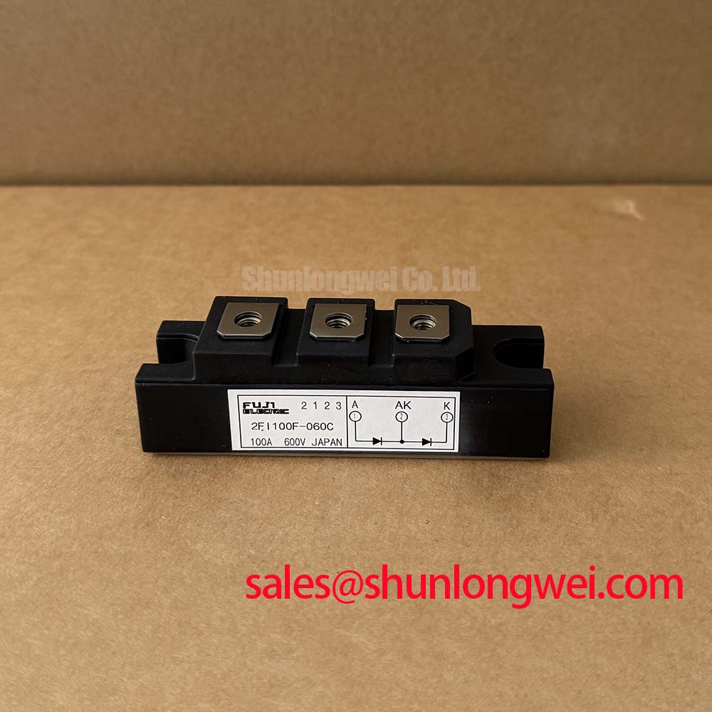
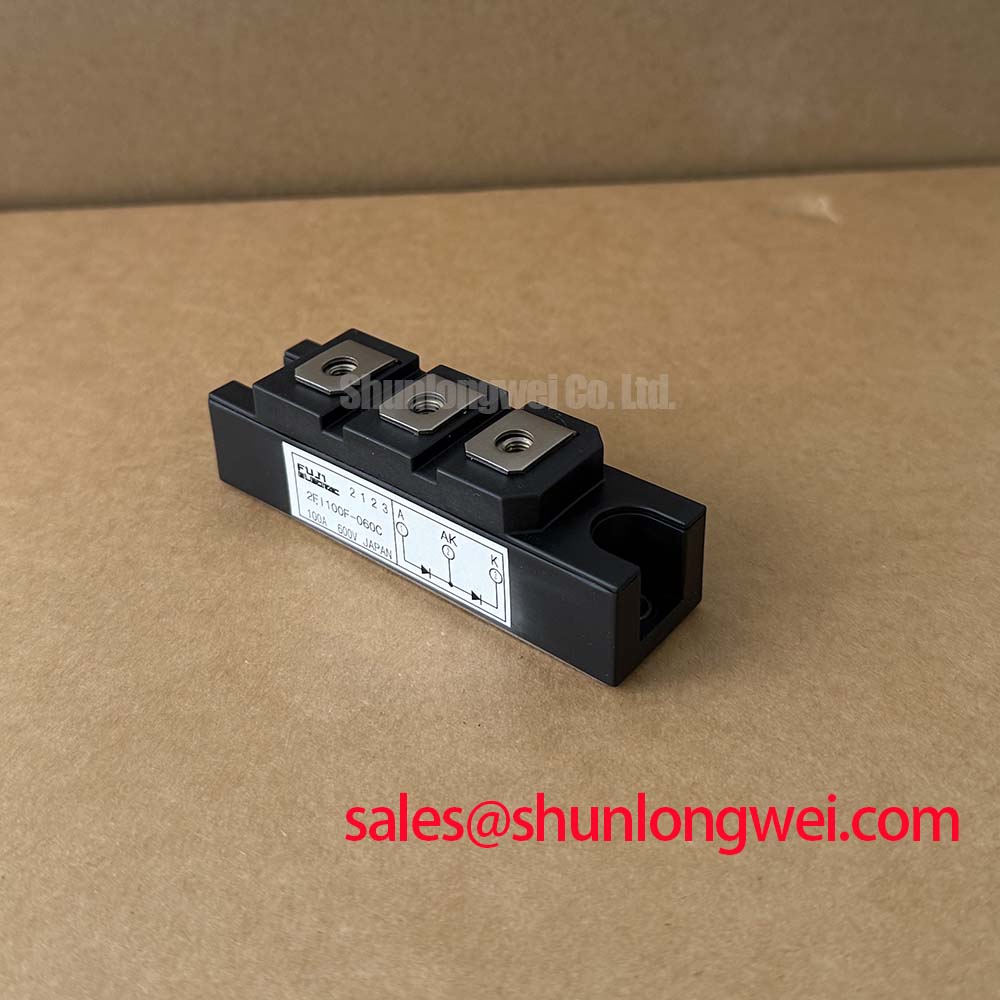
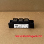
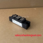
With the module isolated from the DC link, begin incoming inspection by comparing each accessible power-terminal diode path with the original equipment documentation and by checking that no unexpected low-resistance path exists to the heatsink. The Fuji Electric 2FI100F-060C is specified as a diode module with a repetitive peak reverse voltage of 600 V, an average forward-current rating of 100 A per diode element, a specified reverse recovery time of 350 ns, and an isolation-voltage value of 2500 V.
| Official Specification | Value | Unit | Engineering Relevance |
|---|---|---|---|
| Repetitive Peak Reverse Voltage | 600 | V | Maximum stated repetitive reverse-voltage rating |
| Average Forward Current | 100 | A | Specified average forward-current rating per diode element; applicable current depends on operating and thermal conditions |
| Reverse Recovery Time | 350 | ns | Relevant to commutation behavior in switching converters |
| Isolation Voltage | 2500 | V | Specified isolation-voltage value between the electrical circuit and heatsink |
| Junction Temperature Range | −40 to +150 | °C | Official silicon junction operating range |
The 2FI100F-060C should be evaluated as a freewheeling or commutation diode module within the existing power topology, rather than as a gate-driven switching device. It has no published gate-control specification in the supplied official data, so active Miller clamps, negative gate bias, gate damping, and cross-conduction tuning are functions of the companion IGBT or transistor drive circuit, not parameters of this diode module.
For industrial inverter welders and medium-frequency induction-heating power supplies, the diode’s stated 350 ns reverse recovery time is relevant when current transfers between power devices. A reverse-recovery current event can contribute to switching loss, overshoot, and ringing in the surrounding bridge. Design Consideration: inspect the switching waveform with correctly rated differential voltage probing and current measurement, then compare commutation behavior against a known-good channel or the original design record.
Thermal inspection should begin at the mounting interface. Confirm that the module base, heatsink surface, fastening arrangement, insulation hardware where used, and thermal interface material match the equipment service procedure. The stated junction-temperature range of −40 to +150 °C defines the semiconductor operating boundary, but it does not establish an allowable heatsink temperature, cooling capacity, or system current derating rule. Those conditions remain dependent on the complete thermal path and measured operating duty.
💡 Bench Tip: Disconnect stored energy, observe ESD-safe handling, and record cold-state diode readings from a known-good assembly before judging a replacement module.
2FI100F-060C Operational Boundaries and Common Mode Transients
The specified isolation-voltage value is 2500 V. It should not be represented as a reinforced isolation rating above 5 kV, and no common-mode transient immunity value is provided for this module. CMTI is normally specified for isolated gate drivers, digital isolators, or power modules containing driver circuitry; it is not established by the supplied specifications for the 2FI100F-060C.
When a diode module is fitted in a high-frequency bridge, the system integrator should verify the insulation coordination of the complete assembly, including the heatsink, mounting method, busbar clearances, control-board separation, protective-earth arrangement, and probe connection method. The 2500 V isolation-voltage specification is a defined module characteristic, while final clearance and creepage requirements depend on the equipment voltage, pollution environment, insulation system, and applicable end-equipment standard.
Reverse-recovery behavior can also interact with snubber and magnetic components. If oscillation or radiated-noise symptoms appear during commutation, inspect the switching-node waveform for ringing and evaluate the complete current loop. Snubber selection is a system-level Design Consideration and should be validated through measured peak voltage, current, temperature, and switching loss rather than copied from an unrelated converter. For background on magnetic material selection in high-frequency power circuits, see Ferrite Core Materials for High Frequency Switching Power Supplies.
Field Diagnostics and Commissioning of 2FI100F-060C Power Paths
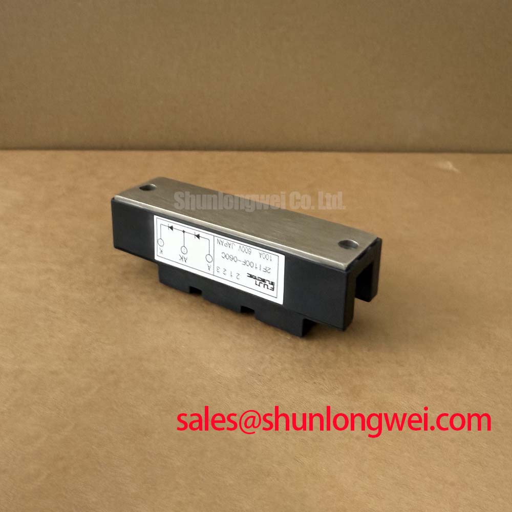
Before energizing a repaired inverter welder or induction-heating supply, verify terminal identity from the original schematic or manufacturer documentation. The supplied official data identifies electrical ratings but does not provide a terminal drawing or an internal connection diagram. Do not infer terminal polarity from package appearance alone. Use the diode-test function to establish the available forward-conduction direction, then compare the result with the removed module and the intended bridge position.
A stable diode-test comparison is useful, but it is not a complete health verdict. A reading that differs from the reference assembly may arise from parallel circuit paths, retained charge in nearby capacitors, test-lead contact quality, or a module condition requiring further evaluation. Isolate surrounding circuitry where the service procedure permits, discharge the DC link safely, and repeat the test from each relevant power terminal to the heatsink. Any continuity to the heatsink that conflicts with the equipment documentation warrants investigation before installation.
Auxiliary Kelvin-emitter routing belongs to the IGBT gate-drive loop. The 2FI100F-060C is specified here as a diode module, so no Kelvin-emitter connection should be assumed. In a bridge that uses separate power and driver returns elsewhere, Design Consideration is to preserve the original low-inductance routing and avoid combining sensitive driver-reference conductors with high-current commutation paths. For broader switching-device troubleshooting concepts, consult The Ultimate IGBT Knowledge Base.
Where a repair assessment identifies a different module footprint, terminal arrangement, voltage class, current rating, or recovery characteristic, compatibility must be confirmed against the actual circuit and mechanical drawing. The 3MBI50SX-120-02 is a separately listed power module for objective specification comparison, not a declared replacement for the 2FI100F-060C.
2FI100F-060C Circuit Protection and Turn Off Overshoot Review
During turn-off of the companion switching device, the voltage seen by the power loop rises above the DC-link level as stray inductance reacts to changing current. In engineering terms, the peak is influenced by DC-link voltage plus the product of loop inductance and current-change rate. This relationship explains why compact, symmetrical busbar geometry and close DC-link decoupling are commonly examined when overshoot is observed. The exact clamping requirement must be determined from measured switching conditions and verified against the 600 V repetitive reverse-voltage limit of the diode module.
Protection coordination should also be reviewed at the assembly level. Semiconductor fuses, current sensing, driver shutdown, DC-link capacitors, contactors, and fault-control timing each have separate roles. A fuse I²t capability cannot be judged from the diode module’s average-current rating alone, and no short-circuit withstand time is supplied for this product. Engineering Recommendation: use the original equipment protection design as the reference, then validate any repaired power stage with controlled commissioning and monitored waveform measurements.
For phase-controlled rectifier sections feeding a welding or induction-heating inverter, conduction angle and line-current harmonics are characteristics of the rectifier, DC-link, and load-control arrangement. The 2FI100F-060C data supports assessment of its stated voltage, current, recovery, isolation, and junction-temperature boundaries, but does not independently establish harmonic performance or EMC compliance for the finished equipment.