

Content last revised on October 21, 2026
Field Diagnostics & Commissioning: Preventing Internal Leadframe Cracking During CXA-0538-A Integration
Before energizing a replacement CXA-0538-A in an electric forklift traction controller, inspect the main power terminals, washer seating, thread engagement, and surrounding board clearance. A terminal that appears electrically sound can still transfer mechanical load into internal copper joins when the cable lug is pulled sideways or when the enclosure experiences vibration.
The installation check should begin with the mating hardware removed and the mounting surface clean. Confirm that the screw enters the intended thread without bottoming, that the washer bears evenly on the cable lug, and that the lug does not rotate while the fastener is tightened. Thread engagement, washer tension, and cable routing should be assessed together because a stiff cable can act as a lever against the terminal during thermal cycling.
Keep heavy conductors supported independently from the inverter board. The power path should remain compact and symmetrical, while flexible service loops should prevent enclosure movement from loading the terminal. Clearance around the terminal is also important: nearby metalwork, shield brackets, and cable glands should not contact the housing when the assembly is moved or subjected to normal machine vibration.
For a field fault, compare the terminal condition with the known-good phase path rather than assigning a single cause to a single symptom. Look for changing contact resistance during controlled mechanical movement, uneven washer impressions, cracked solder or copper joint areas visible from the accessible side, and discoloration near the power connection. Any abnormality should be followed by a continuity and insulation assessment with the board isolated from the rest of the drive.
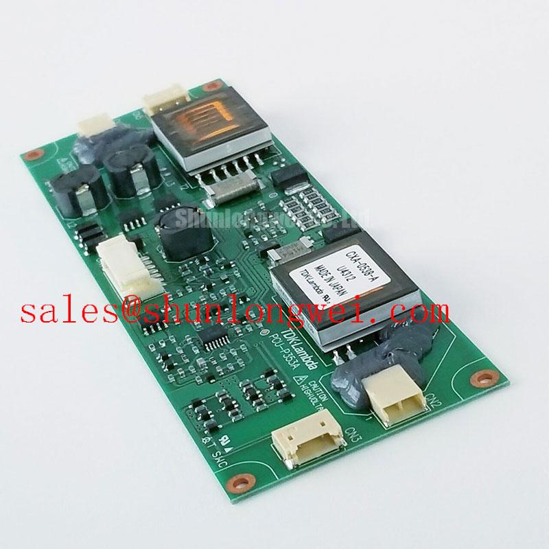
The CXA-0538-A is identified here as a TDK-Lambda Power Module inverter board with a standard industrial voltage rating and standard operating current. The original equipment documentation remains the controlling reference for connector assignment, control supply, protection thresholds, and operating limits. When evaluating a related replacement path, engineers can compare the physical and electrical interface of VI-26W-CU without assuming interchangeability.
Transient Dynamics & Electrical Design: Optimizing Heatsink Contact Pressure and Switching Stress
Uniform heatsink contact is the first mechanical control point for switching stability. Apply the selected thermal interface material as a continuous, thin layer appropriate to the mating surfaces, remove trapped air, and inspect the baseplate for curvature before final assembly. Uneven contact pressure can create local thermal gradients that alter switching behavior and place additional stress on the board and terminals.
Use a staged, diagonal tightening sequence so the baseplate settles progressively rather than bending toward the first tightened screw. The final torque must follow the hardware, heatsink, and original assembly documentation; a generic torque value should not be treated as a CXA-0538-A factory requirement. After mounting, check that the board remains flat, the power terminals are not displaced, and the thermal interface has not been pushed away from the active heat transfer area.
On the electrical side, minimize the commutation loop formed by the DC link, inverter board, and return path. Stray busbar inductance converts rapid current change into turn-off overshoot, so laminated or closely coupled conductors are preferable where the enclosure permits. The system designer should verify peak voltage at the actual terminals during switching tests and compare it with the applicable device and DC-link limits.
Snubber film capacitors should be placed close to the switching current loop, with short, wide connections rather than remote wiring. MOV protection can complement the switching network by absorbing suitable surge energy, but its clamping behavior, continuous voltage rating, energy capability, and coordination with upstream protection must be selected at system level. Long motor cables can produce reflected waves and elevated terminal stress; cable impedance, routing, termination, and filtering should therefore be evaluated together.
For a traction controller, the rectifier or front-end stage also affects the inverter bus waveform. The associated FEC15-24D15 can be reviewed as an auxiliary power-conversion reference, while the actual topology, precharge path, and surge coordination must be checked against the equipment schematic. Thermal enclosure assessment may also consider radiative exchange using the Stefan–Boltzmann law, alongside conduction and forced-air measurements.
⚡ Safety Interlock Note: Disconnect the battery and verify the DC link is discharged before removing power cables or changing heatsink hardware.
Benchtop Waveform Tuning: Mitigating Stress Through Reinforced Insulation Barrier Integrity
Waveform tuning should begin with the isolation boundary, not with gate resistor changes. Confirm the intended reinforced galvanic isolation barrier and its working voltage against the control and power domains; where the system specification requires isolation above 5 kV, the complete barrier, creepage path, connectors, and PCB spacing must be assessed as one assembly.
Common-mode transient immunity is equally dependent on layout and interface construction. A design requirement above 100 kV/µs should be treated as a system-level verification target for the isolator and gate-drive loop, not as an automatic CXA-0538-A rating. During bench testing, monitor both isolated control signals and power-domain references for false transitions, pulse-width distortion, or unexpected reset behavior while the switching node changes state.
Keep the isolated control return path separated from high-current commutation conductors. Minimize capacitive coupling across the barrier, route gate-drive traces as compact forward and return pairs, and avoid placing sensitive logic traces beside the switching node. If a spurious pulse appears, compare probe grounding, isolation supply stability, and signal timing before changing the power stage.
When multiple semiconductor paths operate in parallel, positive temperature coefficient behavior can support static current sharing, but dynamic sharing still depends on gate-loop symmetry, propagation delay, emitter or source impedance, and thermal coupling. Verify current balance with appropriately bandwidth-limited measurements during acceleration and regenerative events rather than relying on low-frequency current readings alone.
For systems using rotating-frame control, the Park transformation provides a useful reference for separating direct, quadrature, and zero-sequence behavior during control analysis. For appliance and compact traction power stages, the discussion of Resonant Topologies in Home Appliances can also help engineers distinguish resonant commutation behavior from a conventional hard-switched waveform. The original CXA-0538-A control interface, supply sequencing, and protection response should remain the governing integration references.