


Content last revised on September 29, 2026
DDB6U215N16L Circuit Protection & Reliability: Calibrating Critical Rate of Rise of Off-State Voltage
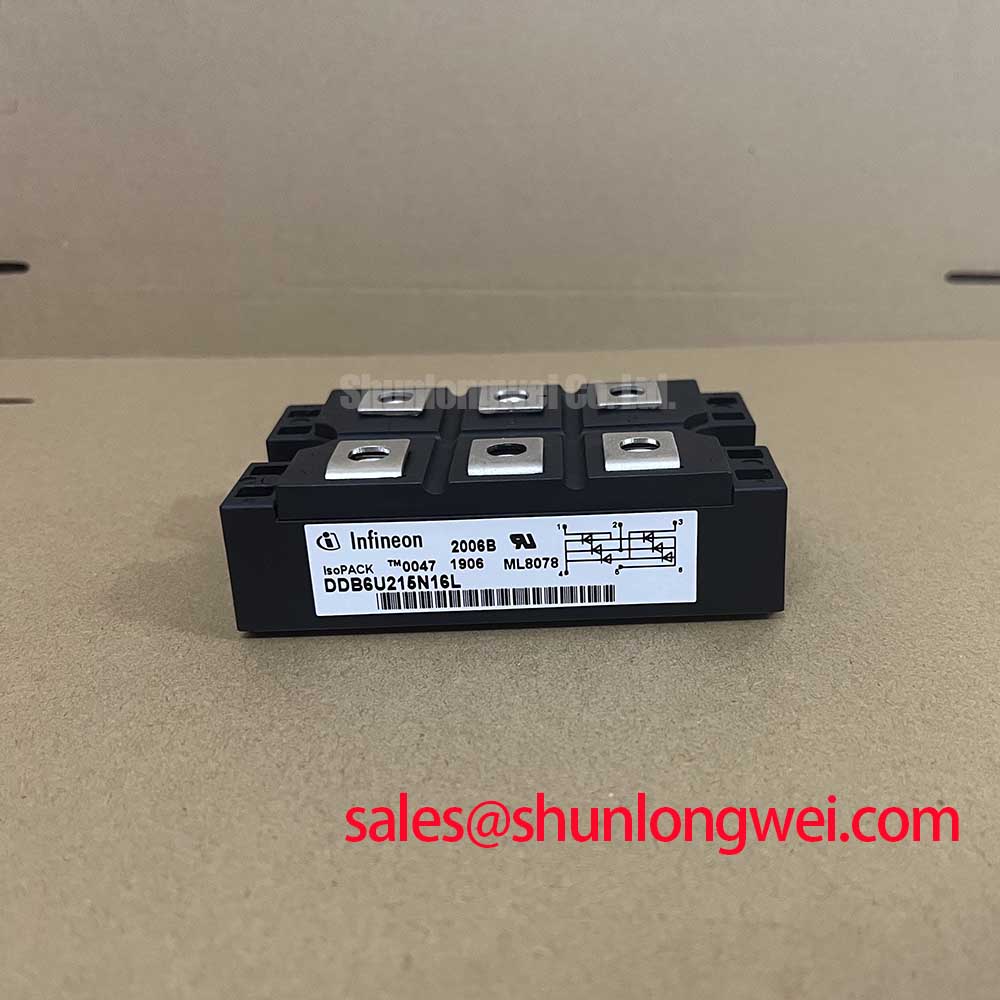
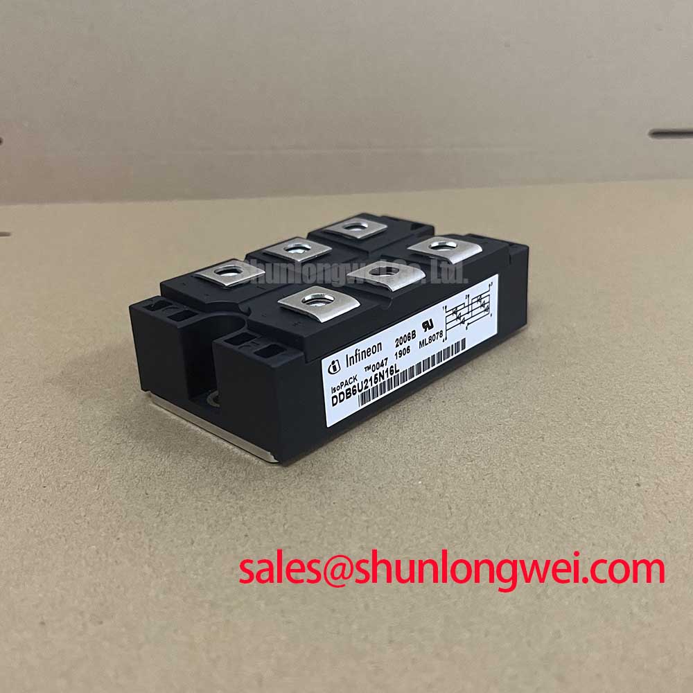
With the equipment isolated and its DC link discharged, compare the cold-state terminal readings of the installed module with the circuit diagram before removing the busbars. For a DDB6U215N16L replacement assessment, confirm the nameplate and connection layout first: the supplied product specifications identify an Infineon Diode Module rated at 1600 V and 215 A in a PowerBlock Module package. These are Official Specification values; they do not establish the module’s internal circuit, terminal assignment, surge capability, or mounting torque.
Start protection work at the terminals, not at a proposed snubber value. Record where each busbar, fuse, and any existing suppression network connects, then compare that arrangement with the equipment schematic and the original module documentation. A diode can experience reverse-voltage transients during commutation, but “critical rate of rise of off-state voltage” and unintended dv/dt turn-on are thyristor concepts. They must not be presented as published characteristics of this Diode Module.
As a Design Consideration, inspect an existing RC network for loose connections or damaged components before deciding whether its behavior needs testing. Snubber component values and any series reactor must be determined from the actual circuit and measured switching waveforms, not inferred from the 1600 V rating. Keep the current path compact to limit parasitic inductance, then verify transient voltage at the module terminals under the equipment’s operating conditions. Infineon’s high-power semiconductor product information provides broader device context, but does not substitute for a DDB6U215N16L-specific limit.
Check semiconductor fuse coordination against the fuse maker’s time-current and I²t data and the applicable module surge data. No DDB6U215N16L fuse I²t table or surge rating is supplied here, so a short-circuit withstand claim would be unsupported. Field Alert: Do not reuse a mounting torque from another PowerBlock module; verify the specified fastener and torque in the original documentation before tightening.
DDB6U215N16L Thermal-Electrical Optimization: Gate Trigger Current Dynamics Practical Tuning
The first gate-circuit check is to establish whether the circuit being serviced actually contains a gate-controlled device. The supplied classification for DDB6U215N16L is Diode Module. A diode has no gate trigger input to tune, so gate trigger current, gate trigger voltage, back-porch current, and multi-pulse firing requirements cannot be assigned to this model. Treat a firing transformer or pulse board found nearby as part of another device’s control path until the schematic proves its connection.
For a stopped rectifier, a practical comparison is to document cold-state readings across the relevant module terminals and compare equivalent positions in a known-good circuit section, where available. Isolate parallel current paths before interpreting a meter reading. A low reading alone does not identify the failed part: busbars, suppression components, and other semiconductor branches can affect an in-circuit measurement. If the readings differ, separate the circuit at approved test points and follow the discrepancy through the schematic.
Mechanical and electrical fit remain distinct checks. Compare the PowerBlock Module footprint, terminal positions, polarity markings, and heatsink interface with the removed assembly; the package name alone does not confirm a drop-in connection. The linked DDB6U180N16RRP_B37 is a comparison candidate, not a verified direct replacement. Its ratings, circuit arrangement, and mounting details require independent comparison before a substitution decision.
DDB6U215N16L Operational Boundaries: Evaluating Thermal Avalanche Margins during High Peak Limits
The confirmed 215 A rating is not a short-duration surge rating. Do not use it to infer a sinusoidal half-cycle peak-current limit, fuse clearing margin, or permissible repetition rate. Those decisions require the model-specific surge-current and thermal data, together with the fuse’s published characteristics. Likewise, “thermal avalanche margin” is not an established specification for this product in the supplied data.
After an overcurrent event, inspect the fuse and power connections and compare the module’s isolated cold-state readings with the circuit’s expected polarity. Check the heatsink contact and fastening condition before returning the assembly to service. If a junction-temperature limit or transient thermal-impedance curve is needed for the restart assessment, obtain it from the applicable manufacturer documentation; the 1600 V and 215 A figures alone cannot answer whether a particular surge was survivable.
In a rectifier system, a linked TT570N16 may be relevant to a separate circuit-position review, but its role and compatibility depend on the actual topology. Infineon’s EconoDUAL 3 information concerns a different module family and must not be used as a source of DDB6U215N16L thermal or mounting limits. For general semiconductor operating principles rather than model-specific life claims, see The Ultimate IGBT Knowledge Base.
DDB6U215N16L Operational Boundaries: Evaluating Harmonic Current Injection and Line Filter Limits
When assessing a medium-frequency induction melting or hardening furnace supply, locate DDB6U215N16L on the power schematic before attributing line harmonics to it. The supplied product information identifies a diode module; it does not establish a firing-angle range or a controlled rectifier function. Firing angle, displacement power factor, and reactive-power demand are properties of the complete converter topology and its controls, not standalone ratings of this part.
As a Design Consideration, compare measured input-current waveforms and filter temperatures with the equipment’s approved operating records after repairs. If the line filter is overheating or the DC link is abnormal, inspect the rectifier connections, fuse state, control signals for any separately gated devices, and filter components rather than assigning a single cause to the diode module. Confirm terminal polarity and physical fit against the original drawings before re-energizing; the final assessment of harmonic limits belongs to the complete equipment under its actual load conditions.