

Content last revised on October 6, 2026
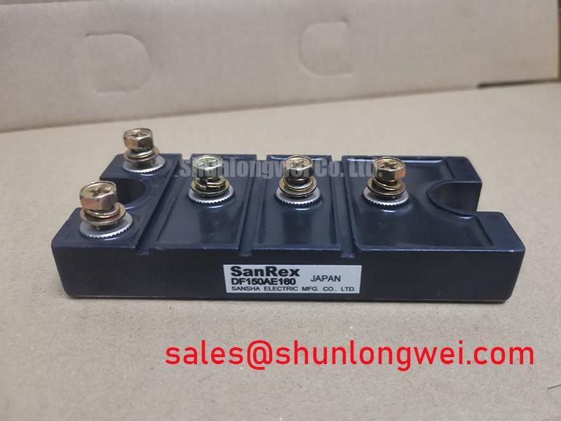
DF150AA160 SanRex 1600 V 150 A Three Phase Bridge Rectifier
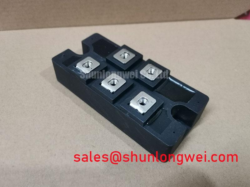
Start the field check with the equipment isolated, then inspect the DF150AA160 housing, terminal condition, mounting surface, and nameplate rating before reconnecting the DC link. The supplied official product data identifies this SanRex, also associated with Sansha Electric, power module as a 150.0 A, 1600.0 V three phase bridge rectifier in a SanRex Power Module package.
For a stalled grid tied Static Var Compensator or thyristor switched capacitor cabinet, this basic identity check prevents a common service error: treating a high current rectifier module as a universal substitute without confirming the original circuit topology, terminal arrangement, cooling method, and protection network. The current and voltage values stated here are official supplied product specifications. They should not be interpreted as a complete operating profile for a specific SVC installation.
| Parameter | DF150AA160 specification | Engineering use |
|---|---|---|
| Manufacturer | SanRex, Sansha Electric | Confirm the equipment bill of materials and service documentation |
| Product category | Three Phase Bridge Rectifier | Suitable topology assessment for AC to DC rectification stages |
| Rated voltage | 1600.0 V | Compare with the rectifier stage voltage and transient environment |
| Rated current | 150.0 A | Compare with load current, duty cycle, cooling, and protection design |
| Package | SanRex Power Module | Verify mechanical footprint, terminal access, and heatsink interface |
Preventing Spurious Faults: Commutation and Reverse Recovery Checks for DF150AA160
In a bridge rectifier service case, inspect the commutation path before blaming the module. The DF150AA160 category indicates a bridge rectifier rather than a gate controlled thyristor device, so the supplied product information does not establish a gate trigger specification, reverse recovery peak current, recovery time, soft recovery class, or an S parameter. Those values must be taken from the applicable SanRex datasheet or the original equipment documentation before a switching loss or EMI assessment is made.
This distinction matters in an SVC or capacitor switching cabinet. A bridge rectifier can be exposed to line commutation, transformer leakage inductance, capacitor charging current, and external switching transients. A replacement decision based only on the 1600.0 V voltage rating and 150.0 A current rating may overlook repetitive peak current, surge current, thermal impedance, insulation requirements, and fuse coordination. Designers should verify every missing dynamic parameter against the actual circuit waveform and the manufacturer’s current documentation.
During field inspection, compare the three AC input terminals and the DC output terminals with the known equipment schematic. Look for loose hardware, heat discoloration, cracked insulation, carbon tracking, and signs of uneven pressure at the terminal interface. A cold resistance check can help identify an obvious shorted junction, but it cannot prove dynamic reverse recovery performance or safe operation at working voltage. If the initial measurement is abnormal, disconnect surrounding capacitors and parallel paths before interpreting the result.
For EMI investigation, use a controlled oscilloscope measurement at the established test points and compare the suspect assembly with a known good signal path. Minimize the measurement loop and follow the probe manufacturer’s voltage category instructions. The technical principles of gate drive, thermal management, commutation control, and power circuit layout are discussed in IGBT Design & Integration; the system engineer must determine which portions apply to this diode bridge topology.
Preventing Spurious Faults: Short Circuit Protection Guidelines for DF150AA160
A semiconductor fuse must be coordinated with the rectifier’s actual short circuit withstand data, not selected from the nominal 150.0 A label alone. The supplied specification set does not include an I²t withstand value for the DF150AA160, a recommended fuse family, clearing energy, or a Type 2 coordination table. These are essential documents for a defensible short circuit assessment and should be obtained from SanRex documentation or the original equipment manufacturer.
For an SVC rectifier cabinet, first record the upstream transformer impedance, available fault current, protective device class, fuse clearing characteristics, DC link capacitance, and conductor arrangement. Then compare the fuse manufacturer’s pre-arcing and total clearing I²t data with the semiconductor manufacturer’s permitted fault energy. The result is system specific because cable impedance, source strength, ambient temperature, and protective relay timing alter the stress applied to the bridge.
Do not treat a fuse that interrupts one fault as proof that the module will remain serviceable after every fault. After a protective event, isolate the supply and discharge stored energy under the equipment service procedure. Inspect the module body, terminals, heatsink interface, fuse holders, busbars, and neighboring capacitors. A visible intact package does not establish junction integrity, while a low resistance reading may be influenced by connected circuit paths.
⚠️ Field Alert: Never loosen or remove power module terminals until the cabinet has been isolated, verified de energized, and all stored energy has been discharged according to the equipment procedure.
When a like for like sourcing review requires a neutral comparison, the PD25016A can be examined as a separate product record, but electrical, mechanical, thermal, and protection compatibility must be verified by the system engineer rather than assumed from product naming or current class.
Assembly Integrity and Layout Architecture: Evaluating Surge Current for DF150AA160
Repeated line energization and capacitor charging can stress a bridge differently from steady state rectification. The supplied official data confirms the 1600.0 V voltage rating and 150.0 A current rating, but it does not provide an ITSM surge current value, a sinusoidal half cycle rating, a junction temperature limit, thermal resistance, or a permissible repetitive surge profile. Those parameters must not be inferred from the two headline ratings.
Before approving the DF150AA160 for a switched capacitor or SVC arrangement, identify whether the module is exposed to transformer inrush, precharge bypass operation, repetitive capacitor charging, or abnormal phase loss. Review the timing of contactors and semiconductor switches, then measure phase current and DC link behavior during a controlled start. If the measured waveform contains a sharp current peak, the system designer should verify the peak against the manufacturer’s surge and thermal data before returning the cabinet to service.
Mechanical assembly is part of the electrical reliability check. Confirm that the heatsink is clean and flat according to the equipment manufacturer’s assembly procedure. Use the specified fastener type, washer arrangement, and tightening sequence from the module or cabinet documentation. Apply thermal interface material only as directed by the relevant assembly instructions; do not substitute a guessed layer thickness or torque value for an approved mechanical specification.
Inspect busbar routing for unnecessary loop area and confirm that phase conductors are supported without transferring mechanical force into the module terminals. Keep high current paths short and balanced where the equipment layout permits, while verifying creepage, clearance, insulation, and enclosure requirements against the applicable installation standard. The Mean Time Between Failures and Reliability Engineering reference can provide general reliability terminology, but it does not establish a DF150AA160 field failure rate or service life.
For procurement, document the exact equipment position, original terminal markings, mounting pattern, rated line voltage, cooling arrangement, and protection devices. This record gives the repair engineer a practical basis for checking whether the SanRex power module can fit the existing rectifier stage without turning a component replacement into an unverified system modification.
DF150AA160 Operational Boundaries: Distinguishing Bridge and Thyristor Controls
The requested gate trigger current, gate pulse rise time, back porch holding current, and multi pulse firing behavior are thyristor control topics. The DF150AA160 is identified in the supplied product data as a three phase bridge rectifier, and no gate terminal, gate trigger current, holding current, or gate pulse specification is provided. Therefore, these parameters should not be assigned to this model or used to create a numerical firing recommendation.
In a cabinet that combines a diode bridge with controlled thyristor branches, separate the two functions on the schematic before troubleshooting. Verify whether the DF150AA160 is used for an uncontrolled rectifier input, a DC link charging path, or another auxiliary conversion stage. The gate driver belongs to the controlled semiconductor section if one is present. A suspected firing fault should be traced through the correct device terminals, driver supply, isolation circuit, pulse transformer or optical interface, and controller timing rather than through the bridge rectifier.
Temperature dependent limits also require the correct manufacturer data. Measure heatsink temperature, airflow or coolant condition, phase current, and enclosure temperature under the actual duty cycle. Then compare those observations with the official thermal curves and operating limits for the exact module revision. A warm package, intermittent trip, or phase imbalance may involve cooling, wiring, upstream protection, load behavior, or a neighboring switching device; the symptom alone does not establish a single failed component.
For replacement approval, retain the original wiring photograph, terminal map, mechanical measurements, and protection settings in the service record. Confirm the voltage and current requirements at the installation level, and require the system engineer to validate insulation, surge, short circuit, thermal, and EMC behavior after repair. A discrete power module does not independently constitute whole equipment compliance with CISPR or EN 55011.