Shunlongwei Co. ltd.
IGBT Module / LCD Display Distributor
Customer Service
+86-755-8273 2562
IGBT Module / LCD Display Distributor
“A growing number of applications require fast and accurate current monitoring, including autonomous vehicles, factory automation and robotics, communications, server power management, class-D audio amplifiers, and medical systems. In many of these applications, bidirectional current sensing is required and needs to be done efficiently with minimal cost.
“
A growing number of applications require fast and accurate current monitoring, including autonomous vehicles, factory automation and robotics, communications, server power management, class-D audio amplifiers, and medical systems. In many of these applications, bidirectional current sensing is required and needs to be done efficiently with minimal cost.
While it is possible to build a bidirectional current sense amplifier (CSA) using a pair of unidirectional current sense amplifiers (CSA), the construction process can be complex and time-consuming. This process would involve combining the two outputs into a single-ended single-ended output rail-to-rail op amp, or using two analog-to-digital converter (ADC) inputs on the microcontroller, which would require additional microcontroller coding and machine cycles. Finally, using two unidirectional CSAs to build a bidirectional CSA—plus the extra parts needed to integrate it into a bidirectional solution consumes more board space, and more components reduces reliability and increases reliability. Large inventory needs. Ultimately, the cost and design schedule may exceed expectations.
To avoid this situation, designers can use an integrated, high-speed, accurate bidirectional CSA. Designers can choose an integrated bidirectional CSA with an internal low-inductance shunt resistor for the most compact solution, or a CSA with an external shunt for more flexible design and layout.
This article will review the implementation requirements of a bidirectional CSA and the advantages of a more integrated approach. Then, the devices from STMicroelectronics, Texas Instruments, and Analog Devices are used as examples to describe in detail, including the key parameters and different characteristics of each device. Finally, this article will show how to start designing with these devices, including the associated reference designs/evaluation kits/development kits, as well as design and implementation tips.
How to use two one-way CSAs
A bidirectional CSA Circuit can be constructed in several ways with two unidirectional CSAs (Figure 1). The Analog Devices MAX4172ESA+T used in the example on the left has no internal load resistors, so discrete devices Ra and Rb are used. In the example on the right, the MAX4173TEUT+T contains a 12 kΩ load resistor to convert its current output to a voltage.
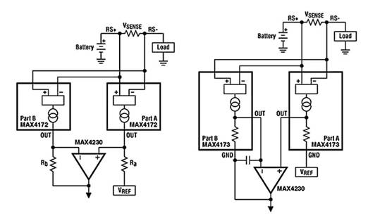
Figure 1: A bidirectional current-sense application consisting of two unidirectional current-sense amplifiers can be implemented by using an external load resistor or an internal load resistor (right). (Image credit: Analog Devices)
Although two load resistors are not required, a 1 nF capacitor is added to the feedback of the MAX4173TEUT+T circuit to stabilize the control loop in part B. In both cases, the output currents from the two CSAs are combined using the MAX4230AXK+T general-purpose op amp.
Both methods have higher part counts than when using a single bidirectional CSA. In addition to the higher part count, the PC board layout is more complicated because the two unidirectional CSAs need to be placed close to the VSENSE resistors.
Application Examples Using Two-Way CSA
Bidirectional CSAs are multifunctional devices with a wide range of applications. For example, in a three-phase servo motor system, two CSAs can be used to determine the instantaneous winding currents for all three phases without any further calculations and without any reference to pulse width modulation (PWM) pulse phases or duty cycles information (Figure 2).
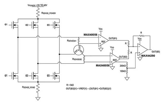
Figure 2: In a three-phase servo motor application, two bidirectional CSAs can connect the sense resistors in phase 1 (RSENSEΦ1) and phase 2 (RSENSEΦ2) to generate a voltage that can represent the current in the third phase winding. (Image credit: Analog Devices)
According to Kirchhoff’s law, the sum of the currents in the first two windings is equal to the current in the third winding. This circuit uses two MAX40056TAUA+ bidirectional CSAs to measure two-phase currents, and the currents are summed by a MAX44290ANT+T general-purpose op amp. Since all three amplifiers have the same reference voltage, a ratiometric method is created.
In another example, a Class D audio amplifier, a bidirectional CSA such as the INA253A1IPW from Texas Instruments can be used to accurately measure the load current of a speaker (Figure 3).
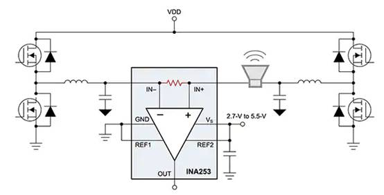
Figure 3: A bidirectional CSA (INA253) can be used to enhance and diagnose speakers in a Class D audio design. (Image credit: Texas Instruments)
Real-time measurements of speaker load current can be used to diagnose and optimize amplifier performance by quantifying key speaker parameters and changes in these parameters, including:
Coil resistance
Speaker impedance
Resonance frequency and peak impedance at resonant frequency
Real-time ambient temperature of the speaker
Board Layout Tips and Shunt Considerations
Parasitic resistance and inductance are issues of concern when implementing current sensing Circuits. In addition, excessive soldering and parasitic resistance can also lead to false detection. Typically a four-terminal current sense resistor is used. If a four-terminal resistor is not selected, the Kelvin pc board layout technique should be used (Figure 4).
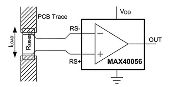
Figure 4: The Kelvin sense trace should be as close as possible to the solder contact pad on the current sense resistor. (Image credit: Analog Devices)
Placing the Kelvin sense traces as close as possible to the solder contacts of the current sense resistor minimizes parasitic resistance. The greater the spacing of the Kelvin sense traces, the more measurement error due to the additional trace resistance will occur.
Proper selection of sense resistors is an important aspect of minimizing parasitic inductance. Since the voltage error is proportional to the load current, package inductance should be minimized. In general, wirewound resistors have the highest inductance values, and standard metal film devices have moderate inductance values. For current sensing applications, low inductance metal film resistors are generally recommended.
The value of the shunt resistor is the result of a trade-off between dynamic range and power dissipation. For high current sensing, a low value shunt is recommended to minimize thermal dissipation (I²R). In low-current sensing, using larger resistor values minimizes the effect of offset voltage on the sensing circuit.
Most CSAs rely on external shunts to measure current, but some CSAs use internal shunts. Although a design using an internal shunt is more compact and has fewer components, there are some trade-offs, including: less flexibility because the shunt value is predetermined; more quiescent current required than an external shunt; The amount of current that can be measured is limited by the capacity of the internal shunt.
High Voltage Precision Bidirectional CSA
Using STMicroelectronics’ TSC2011IST, designers can take advantage of its precision features and use a low-resistance external shunt to minimize power dissipation (Figure 5). This bidirectional CSA is designed to provide accurate current measurements for applications such as data acquisition, motor control, solenoid control, instrumentation, test and measurement, and process control.
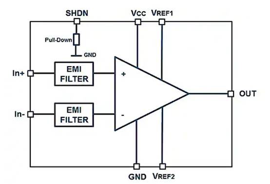
Figure 5: The TSC2011IST includes a shutdown pin (SHDN) for maximum power saving and operates from -40 to 125°C. (Image credit: STMicroelectronics)
The TSC2011IST has an amplifier gain of 60 V/V, an integrated electromagnetic interference (EMI) filter, and a 2 (kV) human body model (HBM) electrostatic discharge (ESD) tolerance (as specified by the JEDEC JESD22-A114F standard). The TSC2011 can detect full-scale voltage drops as low as 10 mV for stable measurements. With a 750 kHz gain-bandwidth product and 7.0 V/µs slew rate, the device ensures high accuracy and fast response.
Designers can quickly get started with the TSC2011IST with the STEVAL-AETKT1V2 evaluation board (Figure 6). The device can sense current over a wide common-mode voltage range of -20 V to +70 V. Features of TSC2011IST:
Gain error: 0.3% max
Offset Drift: 5 µV/°C max
Gain Drift: 10 ppm/°C max
Quiescent current: 20 µA in shutdown mode
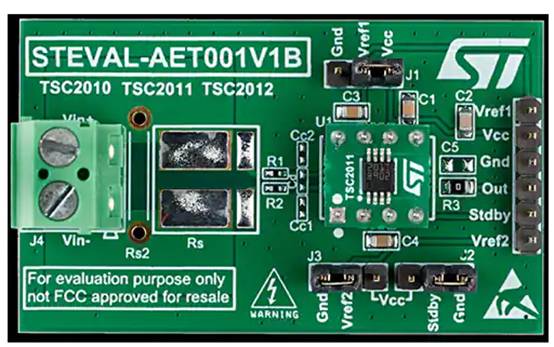
Figure 6: The STEVAL-AETKT1V2 evaluation board consists of the main board and a daughter card containing the TSC2011IST. (Image credit: STMicroelectronics)
Internal bidirectional shunt CSA
Texas Instruments’ INA253A1IPW integrates a 2 mΩ, 0.1% low inductance shunt and supports common-mode voltages up to 80 V (Figure 7). The INA253A1IPW provides designers with enhanced PWM rejection circuitry that rejects large dv/dt signals, enabling continuous, real-time current measurement for applications such as motor drives, solenoid control, and more. The internal amplifier has a precision zero-drift topology with a common-mode rejection ratio (CMRR) greater than 120 dB DC CMRR and 90 dB AC CMRR at 50 kHz.
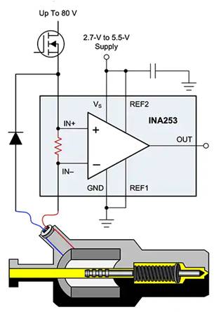
Figure 7: The INA253A1IPW bidirectional CSA in a typical application. The device has an internal shunt and can measure ±15 A continuous current over a temperature range of -40 to +85°C. (Image credit: Texas Instruments)
By accessing the functional pins of the INA253A1IPW using the test points on the associated INA253EVM evaluation board, designers can accelerate the development of system designs based on this CSA (Figure 8). This two-layer board measures 2.4 by 4.2 inches and is fabricated from 1 oz of copper.
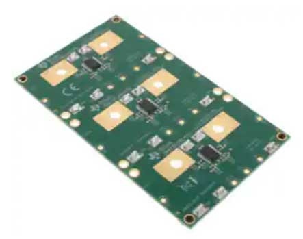
Figure 8: The two-layer INA253EVM device measures 2.4 × 4.2 inches and is fabricated from 1 oz of copper. The bottom layer of the device has no components, just a solid copper ground plane that provides a low impedance path for return current. (Image credit: Texas Instruments)
The pc board includes minimal support circuitry, and functions can be reconfigured, removed, or bypassed as needed. The INA253EVM has the following features:
Three INA253A1IPW devices
All pins are easily accessible
Supports ±15A current through the INA253 CSA’s board layout and construction over the entire -40 to +85°C temperature range
Put the stand on the pc board, it can be used in other configurations than the default configuration
The bottom layer of the device has no components, just a solid copper ground plane that provides a low impedance path for return current.
AEC-Q100 certified bidirectional CSA
To monitor current in full-bridge motor control, switching power supplies, solenoids and battery packs, and automotive applications, designers can use the LT1999IMS8-20#TRPBF from Analog Devices (Figure 9).
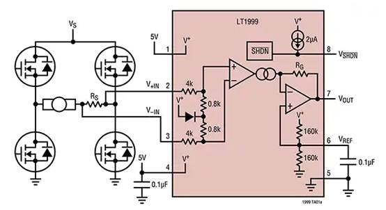
Figure 9: The LT1999IMS8-20#TRPBF is a bidirectional CSA in a full-bridge armature current monitoring application. (Image credit: Analog Devices)
The LT1999IMS8-20#TRPBF is AEC-Q100 qualified for automotive applications and includes a shutdown mode to minimize power consumption. The device uses an external shunt to measure the direction and magnitude of the current. The device scales to produce an output voltage that is referenced midway between voltage and ground. Designers can choose to use an external voltage to set the reference level.
When VSHDN (pin 8) is driven to 0.5 V ground, the LT1999IMS8-20#TRPBF enters a low power shutdown state that consumes approximately 3 μA of current. If the input pins (+IN and -IN) are biased within 0 to 80 V (no differential voltage applied), their current consumption is about 1 nA. An internal 1st-order differential low-pass EMI suppression filter reduces EMI susceptibility and helps eliminate high frequency signals that exceed the device bandwidth.
To facilitate testing the LT1999 series, Analog Devices offers the 1698A demo board. The board amplifies the voltage drop across the onboard current sense resistor and produces a bidirectional output voltage proportional to the current flowing through the resistor. Designers can choose from three fixed gains: 10 V/V (DC1698A-A), 20 V/V (DC1698A-B), and 50 V/V (DC1698A-C).
Bidirectional CSA with PWM Rejection
To improve rejection of common-mode input PWM edges in designs controlling inductive loads such as solenoids and motors, designers can use the MAX40056TAUA+ (Figure 10). As described in Figure 2 above, the MAX40056TAUA+ is a bidirectional CSA that can handle slew rates of ±500 V/µs and above. The typical CMRR of this device is 60dB (50 V, ±500 V/µs input) and 140 dB DC. It has a common-mode range from -0.1 V to +65 V and provides protection against Inductor snapback voltages down to -5 V.
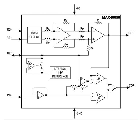
Figure 10: The MAX40056TAUA+ includes an internal 1.5 V voltage reference, enhanced PWM rejection, and an internal integrated window comparator (bottom left, driven by the CIP input) for detecting positive and negative overcurrent conditions. (Image credit: Analog Devices)
The MAX40056TAUA+ device has an internal 1.5 V voltage reference. This reference voltage serves a variety of purposes, including:
Driving differential analog-to-digital converters
Offset the output to show the direction of the detected current
Direct current into external load to mitigate the effects of performance degradation
Designers can override the internal reference with a higher external voltage reference when higher full-scale output swing is useful or when the supply voltage is higher than 3.3 V. Finally, designers can use an internal or external reference to set thresholds to trip the integrated overcurrent comparator, providing an instant overcurrent fault signal.
The MAX40056EVKIT# Evaluation Kit for the MAX40056TAUA+ provides designers with a proven platform for developing high-precision, high-voltage, bidirectional CSA applications such as solenoid drivers and servo motor controllers.
in conclusion
A wide variety of applications require fast, accurate current monitoring, ranging from autonomous vehicles, factory automation, and robotics, to communications, server power management, class-D audio amplifiers, and medical systems. In many cases, bidirectional current sensing is required.
Fortunately, designers can choose from a variety of integrated bidirectional CSAs and their associated development platforms to quickly and efficiently implement fast, accurate bidirectional current monitoring.
The Links: DP15F1200T0101910 LM215WF3-SLG1