


Content last revised on April 21, 2026
Infineon FF400R06KE3 | 600V Dual IGBT Module Engineered for High-Frequency Power Conversion
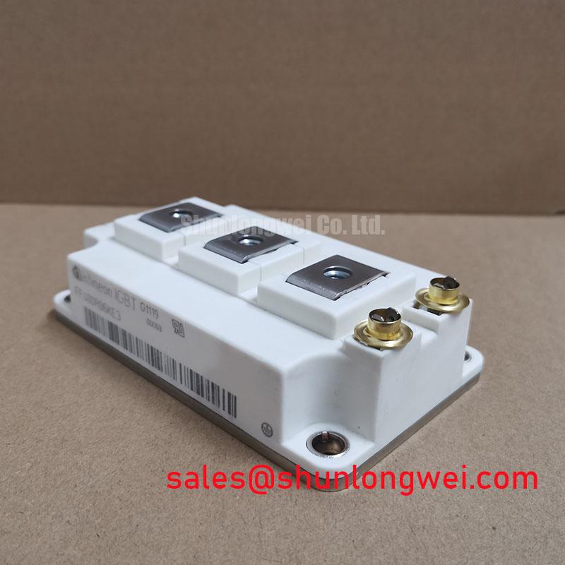
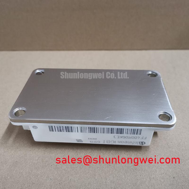
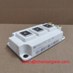
The Infineon FF400R06KE3 is a high-performance 600V, 400A dual IGBT module designed for engineers who require exceptional efficiency and reliability in high-frequency power conversion systems. Encapsulated in the industry-standard 62mm package, this module integrates Infineon's advanced TRENCHSTOP™ IGBT3 and Emitter Controlled 3 diode technologies to deliver a superior solution for demanding applications. Its robust design is optimized to minimize both conduction and switching losses, enabling higher power density and improved thermal performance in compact system designs.
Technical Deep Dive: TRENCHSTOP™ IGBT3 and EC3 Diode Synergy
At the core of the FF400R06KE3 lies the sophisticated Infineon TRENCHSTOP™ IGBT3 technology. This technology represents a significant leap from older planar IGBT structures. By creating a trench gate and a field-stop layer, it achieves an almost ideal carrier distribution within the silicon. The direct engineering benefit is a remarkably low collector-emitter saturation voltage (VCE(sat)) of just 1.45V (typical at 25°C). This low VCE(sat) directly translates to reduced conduction losses, which is a critical factor in applications with high duty cycles.
Complementing the IGBT is the Emitter Controlled 3 (EC3) freewheeling diode. This diode is engineered for soft, fast switching with low reverse recovery charge (Qrr). The synergy between the fast-switching IGBT3 and the soft-recovery EC3 diode is crucial for minimizing switching losses and reducing electromagnetic interference (EMI). This combination allows designers to push operating frequencies higher without incurring prohibitive thermal penalties, a key requirement for modern, compact power converters. Understanding this interplay is essential, as detailed in our guide to IGBT selection for high-frequency designs.
Application Scenarios and Engineering Value
The specific characteristics of the Infineon FF400R06KE3 make it an ideal choice for several high-power applications:
- Welding Power Supplies: In high-frequency welding applications, the module's fast switching capability and low losses enable precise control over the welding arc, leading to higher quality welds and improved energy efficiency. Its robust thermal design ensures reliability even under the strenuous load cycles typical of industrial welding.
- Uninterruptible Power Supplies (UPS): For enterprise-grade UPS systems, efficiency and reliability are paramount. The FF400R06KE3's low total power loss minimizes cooling requirements and reduces operating costs. Its high power density allows for more compact UPS designs, a valuable benefit in space-constrained data centers.
- Solar Inverters: The module's efficiency is critical in solar applications for maximizing the energy harvested from PV arrays. The ability to operate at higher switching frequencies allows for the use of smaller and lighter magnetic components, reducing the overall size and cost of the solar inverter.
Key Parameter Overview
The following table provides a summary of the critical electrical and thermal parameters for the FF400R06KE3. For a comprehensive list of specifications and performance graphs, engineers should consult the official Infineon FF400R06KE3 datasheet.
| Parameter | Value |
|---|---|
| Collector-Emitter Voltage (V_CES) | 600 V |
| Continuous DC Collector Current (I_C) @ 70°C | 400 A |
| Nominal Collector Current (I_C nom) | 400 A |
| Collector-Emitter Saturation Voltage (V_CE(sat), typ. @ 400A, 150°C) | 1.70 V |
| Gate Threshold Voltage (V_GE(th)) | 4.9V - 6.5V |
| Maximum Junction Temperature (T_vj max) | 150°C (175°C overload) |
| Package | 62mm Dual Module |
Selection Guidance: FF400R06KE3 vs. Higher Voltage Alternatives
When selecting from the broader family of 400A IGBT modules, it is crucial to match the voltage class to the application's DC bus voltage. The FF400R06KE3, with its 600V rating, is optimized for systems with DC link voltages up to approximately 400V, providing a necessary safety margin.
For applications requiring higher bus voltages, such as 690V AC industrial motor drives, a 1200V module like the FF400R12KE3 would be the appropriate choice. While both modules offer the same current rating, the 1200V version has a higher VCE(sat) due to its thicker drift region needed to block the higher voltage. Using a 1200V module in a 400V system would result in unnecessarily high conduction losses. Conversely, using the 600V FF400R06KE3 in a system with a bus voltage exceeding its rating would lead to catastrophic failure. This highlights the importance of carefully decoding IGBT datasheets to ensure proper component selection for optimal system performance and reliability.
Frequently Asked Questions (FAQ)
1. What are the key considerations for the gate drive design for the FF400R06KE3?
To leverage the module's fast-switching TRENCHSTOP™ IGBT3 technology, a well-designed gate driver is critical. It should be capable of providing high peak currents to quickly charge and discharge the IGBT's input capacitance, minimizing switching times. A clean gate voltage of +15V for turn-on and a negative voltage (e.g., -8V to -15V) for turn-off is recommended to ensure full enhancement and prevent parasitic turn-on, especially in noisy, high dV/dt environments.
2. Can the FF400R06KE3 modules be paralleled for higher current output?
Yes, these modules can be paralleled, but careful design is essential. The positive temperature coefficient of the VCE(sat) in TRENCHSTOP™ IGBTs provides a degree of self-balancing for static current sharing. However, to ensure dynamic balance during switching, a symmetrical PCB layout for the gate drive paths and the main power connections is paramount. Mismatches in gate drive impedance or stray inductance in the power path can lead to unbalanced switching and potential failure of one of the parallel modules.
For further inquiries about implementing the Infineon FF400R06KE3 in your design, please contact our technical team for expert support.