Content last revised on October 12, 2026
FP40R12KE3BOSA1 Maintenance and Compatibility Checks
- Isolate the equipment, verify that the DC link is discharged, and compare the installed module marking with FP40R12KE3BOSA1 before disconnecting its connections.
- Record cold resistance measurements across accessible power paths with the gate circuit in a defined state, identifying parallel circuit paths that could influence the readings.
- Inspect the heatsink interface, mounting surfaces, and surrounding airflow path for contamination, uneven seating, or displaced thermal interface material.
- Check the existing driver schematic and terminal assignment before reconnecting gate wiring or applying auxiliary power.
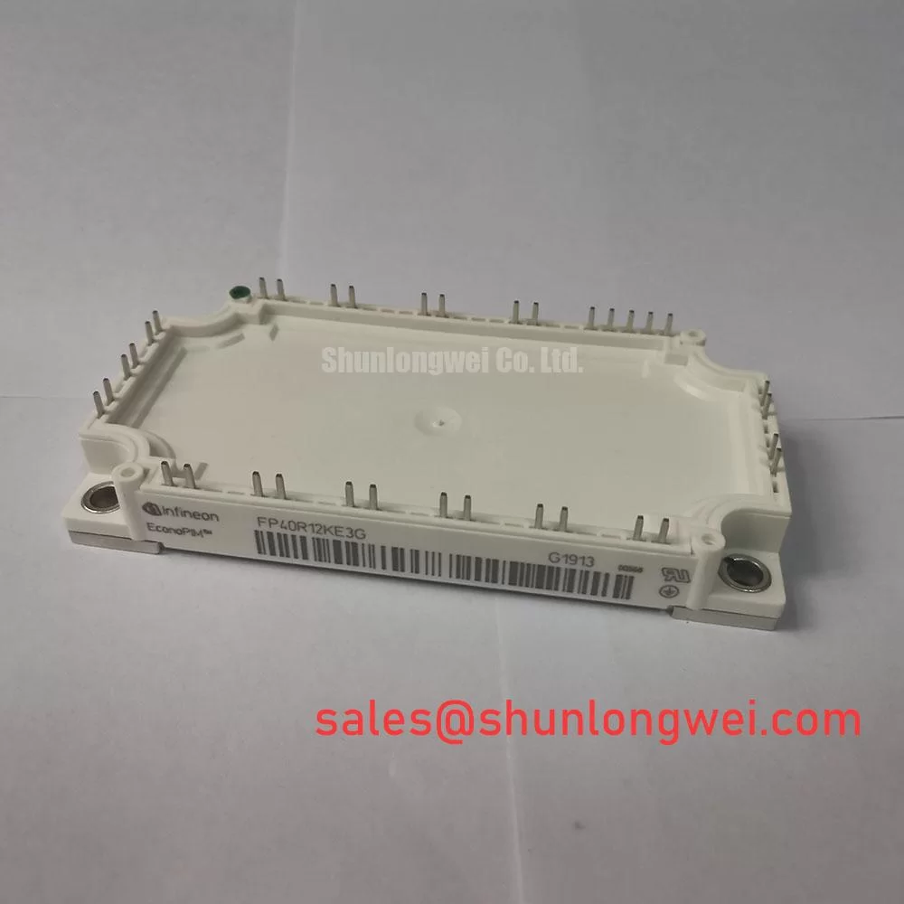
The Infineon FP40R12KE3BOSA1 is a 1200 V, 40 A IGBT module. Maintenance evaluation should connect those electrical ratings with the actual converter schematic, cooling arrangement, and protection circuit. A matching voltage and current designation is an initial screening criterion, not evidence that another module will share the same terminal layout or switching behavior.
| Product characteristic | Official Specification |
|---|---|
| Product model | FP40R12KE3BOSA1 |
| Manufacturer | Infineon |
| Voltage rating | 1200 V |
| Current rating | 40 A |
| Package / case | Module |
Consult Datasheet for the internal circuit, terminal drawing, rating conditions, gate limits, thermal characteristics, and mounting instructions. The integration guidance below is identified as Design Consideration or Engineering Recommendation; it does not add manufacturer specifications to the product.
Transient Dynamics & Electrical Design: DC-DC Converter Interleaving and Ripple Reduction on FP40R12KE3BOSA1
Design Consideration: Trace the converter power paths before assessing interleaving, because battery charging and discharging require a circuit that supports the intended direction of energy transfer. Bidirectional DC power flow is not, by itself, four-quadrant operation; that description also depends on the voltage and current polarities supported by the complete converter. The FP40R12KE3BOSA1 rating does not establish either capability.
For compatibility assessment, commercial string inverters and micro-grid energy storage equipment are potential evaluation contexts, subject to circuit topology, terminal compatibility, cooling capacity, and protection requirements. Start with the equipment schematic rather than assigning this module a presumed role. Establish which switches carry charging current, which carry discharging current, and where freewheeling current flows during switching transitions.
In an interleaved stage, displaced switching events can reduce combined ripple at a shared connection, but individual branches still carry their own ripple current. Compare branch-current waveforms at equivalent load conditions and inspect whether their timing remains consistent through operating transitions. Unequal current sharing can arise from control timing, sensing offsets, passive-component differences, or connection impedance. Investigate these possibilities together rather than treating a hotter module as proof of an internal defect.
During peak-shaving duty, correlate current records with case or heatsink temperature trends. Repeated charge and discharge transitions can produce changing semiconductor losses and thermal excursions even when average output appears steady. An Engineering Recommendation is to capture representative operating transitions rather than only a stable full-load interval. The equipment designer should evaluate the resulting loss profile against the applicable thermal model and cooling conditions.
For switching measurements, use appropriately rated probes and controlled connections so that probe placement does not dominate the observed ringing. Minimize the commutation-loop area to reduce inductive overshoot, while keeping gate wiring separated from high-current switching paths. Determine conductor spacing from working voltage, the installation environment, and the applicable equipment requirements; the module voltage designation alone does not establish cabinet clearance or creepage dimensions.
Driver isolation deserves attention when current sharing changes unexpectedly during fast transitions. As a Design Consideration, compare the optocoupler or digital isolator common-mode transient immunity with the measured switching environment, including the installed layout. Check driver output behavior, auxiliary-supply disturbance, and sensing signals at the same event. A control upset and power-loop ringing can occur together without having the same origin.
If the equipment also contains a phase-controlled rectifier, evaluate its conduction-angle settings and input-current distortion separately from downstream interleaving. Reduced DC ripple does not demonstrate reduced grid harmonics. For broader device-family context, the Infineon IGBT Modules Overview provides manufacturer information; specific circuit decisions still require the characteristics of the exact device.
Transient Dynamics & Electrical Design: Mitigating Bolted Contact Oxidation and Checking Gate-Power Integrity on FP40R12KE3BOSA1
Engineering Recommendation: Audit any bolted connections in the module’s external current path using a four-wire micro-ohmmeter, with the equipment isolated and measurement points documented. Separate the resistance of the joint from the resistance of cables, busbars, and other connections wherever access permits. A resistance target must come from the equipment or connection specification, not from a generic threshold assigned to this module.
Repeat measurements with comparable probe placement and joint temperature. Surface films, changing contact pressure, and movement of the measurement points can influence very low resistance readings. Record the connection location and test conditions so that later maintenance results describe a trend rather than a collection of unrelated measurements. Do not apply a presumed power-terminal fastening method to a different terminal construction.
Thermography provides a useful complementary check under a controlled operating condition. Compare equivalent current paths and account for surface emissivity, reflections, airflow, and access limitations. A localized temperature rise can justify further investigation of contact condition or current distribution, but it does not independently identify oxidation. Inspect mating surfaces and hardware in accordance with the equipment service procedure before deciding whether cleaning, reassembly, or another intervention is appropriate.
Maintenance Note: Trend connection temperature and check heatsink airflow during scheduled inspections before treating an isolated thermal image as evidence of module deterioration.
Set inspection intervals from operating hours, environmental contamination, load cycling, and previous condition records rather than inventing a replacement schedule for FP40R12KE3BOSA1. During planned shutdowns, examine accessible thermal interface edges and mounting condition for evidence of disturbance or uneven seating. If removal is necessary, follow the specified surface preparation and reassembly procedure; adding fresh compound over an uncontrolled existing layer can change the interface rather than restore it.
Gate-power integrity is a separate investigation from terminal heating. Where the existing driver uses a bootstrap supply, its charge budget should include the driven gate charge under the intended switching conditions, driver quiescent consumption, leakage, and the longest interval without recharge. Account for capacitance tolerance and operating-temperature behavior. The allowable supply droop follows from the driver’s operating requirements and undervoltage behavior, so capacitor selection belongs to the complete driver calculation rather than a universal module-specific value.
Check bootstrap recharge opportunities during startup, prolonged duty commands, and fault recovery, not just during repetitive switching. A supply that recovers adequately in steady operation can behave differently during a transition. Observe the high-side supply relative to its local reference with suitable instrumentation, and correlate any disturbance with the gate output before attributing the symptom to the power module.
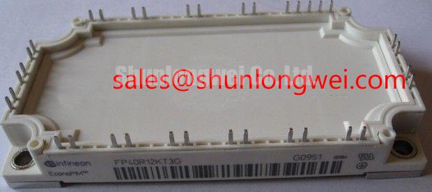
For replacement evaluation, FP40R12KE3G is a related model to compare, not an established drop-in substitute. Compare the internal circuit, terminal mapping, mechanical fit, gate-drive requirements, diode characteristics, and thermal ratings against the original assembly. A purchasing comparison should preserve the complete ordering designation and identify any equipment revision that affects compatibility.
FP40R12KE3BOSA1 Thermal-Electrical Optimization: High-Speed Fuse Coordination and Arcing Voltage
Design Consideration: Coordinate the semiconductor fuse with the complete fault path, including DC-link capacitance, conductor inductance, supply contribution, and the gate-driver protection sequence. Fuse total clearing I²t is relevant to coordination, but it is not a standalone guarantee that an IGBT will survive a short circuit. Semiconductor damage can develop before the upstream fuse completes interruption.
Distinguish the fuse’s pre-arcing behavior from its total clearing behavior. During interruption, fuse arcing voltage adds another electrical stress that must be evaluated against the circuit’s voltage capability and suppression arrangement. Use fuse-manufacturer data appropriate to the applied DC voltage and prospective fault conditions. The protection review should include both interruption capability and the voltage appearing across affected components.
Do not assume a module sub-cycle withstand rating from its 40 A current designation. Coordinate any documented semiconductor short-circuit capability with driver detection, propagation delay, turn-off behavior, and residual circuit energy under matching conditions. Preventing case rupture requires an equipment-level fault assessment and suitable containment; fuse selection alone cannot establish that outcome.
For practical troubleshooting, retain fault logs and inspect the driver’s latched status before resetting the equipment. Compare the protection sequence with measured current and DC-link voltage records where safe test facilities permit. Repeatedly energizing a suspected fault to reproduce it can destroy useful evidence. Controlled testing should distinguish a driver-command problem, an external short circuit, and an interruption-related transient without presuming a single cause.
Transient thermal impedance is useful when evaluating short load pulses that a steady-state thermal calculation can obscure. As an Engineering Recommendation, combine the operating loss history with the applicable transient thermal model, retaining its reference boundary and time dependence. A heatsink sensor cannot directly resolve the fastest junction-temperature excursion. Cooling condition and accumulated temperature therefore belong in the same assessment as pulse duration.
Keep resonant-converter behavior separate from hard-switched fault analysis. The technical discussion in Resonant Topologies in Home Appliances explains why topology changes switching stress; it is background context, not evidence that FP40R12KE3BOSA1 is qualified for a particular resonant circuit. Apply the actual equipment schematic when identifying current paths and protection requirements.
After a protection intervention, inspect nearby insulation surfaces for contamination and moisture before restoring service. Where enclosure temperature changes create condensation risk, evaluate environmental control through the equipment maintenance procedure. For an installation with an altitude requirement, obtain applicable manufacturer guidance rather than assigning a universal voltage derating or cosmic-ray failure allowance. Return the assembly to service only after its connection condition, cooling path, driver operation, and protection sequence satisfy the equipment’s acceptance procedure.