

Content last revised on October 15, 2026
PM50RLA120 Identification and Pre-Service Checks
- Isolate the equipment, verify that the DC link is discharged, and disconnect external power paths before comparing cold terminal measurements.
- Check the PM50RLA120 marking against the equipment bill of materials and identify every power and control connection from the approved circuit drawing.
- Inspect the heatsink contact surface, mounting hardware, terminal supports, and airflow path before disturbing the installed module.
- Check auxiliary supply connections and control-board isolation before reconnecting the high-voltage power stage.
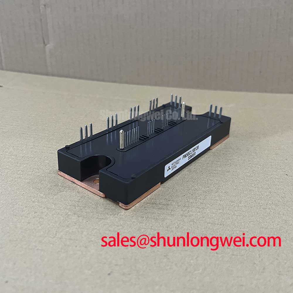
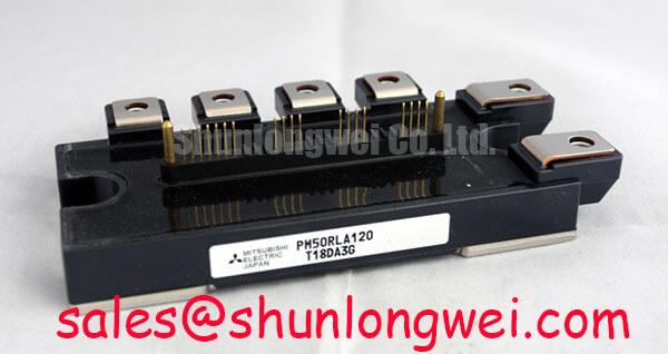
The Mitsubishi Electric PM50RLA120 is an IPM (Intelligent Power Module) with a 1200 V voltage rating and 50 A current rating. These ratings are subject to the datasheet conditions, rather than universal operating limits for an installed assembly. For a maintenance replacement, these identifiers establish the starting point; control-interface compatibility, mounting geometry, and thermal contact still determine whether the assembly can return to service.
| Product attribute | Specification / integration guidance |
|---|---|
| Model | PM50RLA120 |
| Manufacturer | Mitsubishi Electric |
| Rated voltage | 1200 V |
| Rated current | 50 A, subject to datasheet rating conditions |
| Product category | IPM (Intelligent Power Module) |
| Additional integration requirements | Consult Datasheet for terminal assignments, rating conditions, control supplies, protection timing, mechanical dimensions, and assembly limits. |
Compatibility assessment may include an industrial inverter welder or a medium-frequency induction-heating supply, provided its circuit topology and operating conditions match the module requirements. This is an application assessment, not a statement that the PM50RLA120 is a universal replacement for either equipment class.
PM50RLA120 Circuit Protection & Reliability: Gate-Drive Resistance and Replacement Compatibility
Trace the legacy board’s output connections before treating any resistor as an adjustable gate-drive component. Design Consideration: an intelligent power module must be evaluated through its documented control interface, rather than approached as a bare IGBT with externally accessible gate terminals. A resistor beside an input connector can serve signal conditioning or current limiting; changing it does not necessarily change the internal gate-drive resistance.
When a repair proposal calls for separate turn-on and turn-off resistance adjustment, first establish where those resistors actually sit in the circuit. External gate-resistor tuning belongs only to an architecture that exposes the relevant gate connections and permits that adjustment. For the PM50RLA120 installation, preserve the approved input network unless the equipment documentation supports a modification. This prevents a discrete-module retrofit procedure from being applied to an incompatible IPM interface.
For an approved interface modification, evaluate switching behavior and control integrity together. Slower transitions can reduce ringing while increasing switching dissipation; faster transitions can increase sensitivity to wiring inductance and coupling. The appropriate balance is system-determined. Record the measurement reference, operating load, DC-link condition, and module temperature so that comparisons describe the same test condition rather than unrelated oscilloscope captures.
Keep control wiring separated from high-current switching conductors and preserve the return path associated with each control signal. Where switching noise appears at the interface, compare the signal at the controller output and module input using suitably rated measurement equipment. A disturbed input waveform can originate in grounding, routing, supply behavior, or connector condition; it should not automatically trigger a resistor change.
Use the manufacturer’s Mitsubishi Electric Power Semiconductors & High-Power Modules resources to distinguish IPM interface requirements from conventional power-module drive arrangements. That distinction matters when reviewing a modernization proposal: similar voltage ratings do not establish matching protection behavior, terminal functions, or control-board compatibility.
A comparison with CM2500DY-24S should therefore remain a component-architecture comparison, not a same-specification replacement recommendation. Procurement should retain the exact PM50RLA120 designation unless engineering has approved a redesigned assembly. A useful purchasing record includes the terminal drawing, mounting arrangement, interface connector details, and equipment revision alongside the requested part number.
During fault investigation, preserve evidence from the original drive board before replacing components. Note which protection indication appeared, whether the event occurred during startup or load change, and whether multiple switching positions show similar behavior. These observations help separate a local connection problem from a shared supply or control issue without assigning a single cause to a nonspecific symptom.
PM50RLA120 Thermal-Electrical Optimization: Auxiliary Power Sequencing and Transient Control
Verify that the auxiliary control supply is established and the equipment’s inhibit logic is functioning before enabling the DC-link power stage. Engineering Recommendation: validate startup, shutdown, and interrupted-supply behavior against the approved IPM control sequence. Do not impose an external negative gate-bias arrangement on the PM50RLA120 simply because a separate IGBT driver used one.
Observe the auxiliary voltage at the module-side connection during startup, switching activity, and supply removal. Cable resistance, connector deterioration, and local supply loading can produce behavior that is not visible at the power-supply output terminals. Correlate any supply disturbance with the controller’s enable state and fault response. The objective is a controlled inhibit during an abnormal supply condition, with restart governed by the equipment’s documented recovery sequence.
Undervoltage interlock behavior requires attention at the system boundary. Confirm that the controller does not continue issuing effective switching commands while its associated interface is losing power. Check shutdown as carefully as startup, particularly where separate auxiliary supplies decay at different rates. Signal activity during partial power conditions should be evaluated against the interface circuit rather than accepted because the machine starts normally.
For the power connections, minimize commutation-loop area to limit inductive overshoot, then verify the resulting terminal waveform under the intended operating conditions. Busbar shape, joint placement, and capacitor connection length all affect the loop. A fixed inductance target is not a PM50RLA120 factory specification; the acceptable arrangement follows from the complete converter and its measured switching stress.
Where the equipment includes a snubber, retain its intended electrical placement and inspect its connections during service. A capacitor located physically near the module can still have an ineffective current path if its connecting conductors make a large loop. Any change in capacitor type or placement should be evaluated for pulse duty, heating, and interaction with the existing circuit, not selected solely by capacitance.
Review complementary power stages separately. The CM100MXA-24S can be considered in a broader semiconductor comparison, but its suitability for an adjacent switching stage depends on its own circuit configuration and ratings. Its presence in a product comparison does not establish that it is a rectifier or a compatible companion for this IPM.
If the host equipment includes regenerative braking, trace the actual energy path through the DC link, braking switch, and resistor assembly. Do not assume that the PM50RLA120 provides a braking function merely because the cabinet contains a braking resistor. Check resistor connections, thermal protection, and controller operation against the equipment schematic; energy absorption capability belongs to that complete assembly.
Thermal observations should accompany electrical checks. Compare heatsink and terminal temperature trends under repeatable load conditions, allowing for airflow and ambient differences. A hotter connection may justify inspection for contact deterioration, while a broader heatsink rise may direct attention toward cooling performance. Neither observation alone establishes an internal module fault.
PM50RLA120 Assembly Integrity & Layout: Isolation Screening, Creepage, and Thermal Contact
Remove dust and contamination from accessible insulating surfaces before assessing the condition of terminal-to-baseplate isolation. Design Consideration: surface leakage, moisture, connected circuitry, and internal insulation can all influence an insulation measurement. A single resistance reading cannot establish the condition of an internal ceramic substrate or confirm the absence of microscopic cracking.
Use an approved insulation-test procedure that identifies the terminals to be grouped, the circuits to be disconnected, the test waveform, and the permitted stress. Keep control electronics outside the test path unless the manufacturer’s procedure explicitly includes them. Do not substitute a generic high-voltage insulation-tester setting for a module-specific test, or treat dielectric-withstand testing and insulation-resistance measurement as interchangeable.
Inspect terminal spacing after the power conductors are secured, not only while the module is bare. Cable lugs, displaced washers, unsupported busbars, and conductive debris can alter the effective clearance or creepage path. Clearance is the through-air separation; creepage follows an insulating surface. Their required values depend on the equipment’s insulation coordination and environmental conditions rather than the module’s voltage rating alone.
Assess contamination where it actually accumulates: around terminal shoulders, beneath protective covers, and near airflow entry points. Cleaning should follow an approved method that leaves no conductive residue and does not damage markings or insulating surfaces. After movement from cold storage into a warmer workshop, allow the assembly to reach suitable dry conditions before electrical testing; visible dryness at the enclosure does not establish that concealed surfaces are dry.
For mounting, clean the heatsink interface and check for burrs, raised damage, or uneven seating. Apply the specified thermal interface material with the coverage and thickness required by the approved assembly procedure. Excess material is not a substitute for flat contact, and dry areas should not be concealed by tightening the mounting hardware further. Avoid introducing an additional pad or washer stack that changes the intended mechanical support.
Use the documented tightening sequence and torque with a calibrated tool. Support connected busbars so that terminal fasteners do not pull the module into alignment with a displaced conductor. Separate the mounting check from the terminal-joint check: they control different mechanical loads, and neither should be adjusted by feel.
Maintenance Note: Trend terminal temperature and cooling airflow during planned inspections, and investigate changes before simply retightening connections.
Set inspection intervals from equipment duty, contamination exposure, and recorded condition rather than assigning the module an invented service life. When thermal performance deteriorates, examine fan operation, filter loading, heatsink blockage, and accessible interface condition. If disassembly is justified, document the contact pattern and renew the thermal interface according to the assembly procedure before recommissioning.
The Mitsubishi Electric Global Semiconductor Device Technologies portal provides manufacturer context for semiconductor documentation. For a broader discussion of switching paths, the Peak Efficiency in Solar and Energy Storage guide offers topology background; it does not establish a five-level configuration or application approval for the PM50RLA120.
Close the maintenance record with the installed part designation, interface checks, mounting procedure, insulation-test method, and comparable temperature observations. Retain photographs of terminal routing and cooling access so the next inspection can identify physical changes without reconstructing the assembly history.