


Content last revised on September 24, 2026
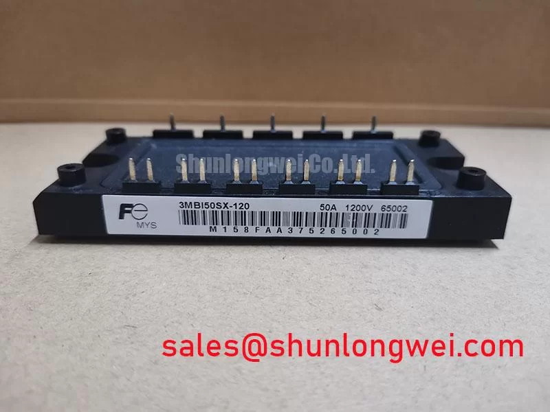
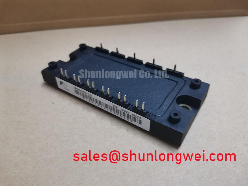
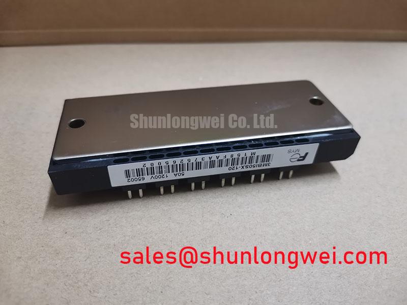
With the DC bus fully isolated and discharged, check the module markings, inspect the terminal area for mechanical damage, and compare the cold-state terminal behavior with a known-good reference before applying a test voltage. The 3MBI50SX-120 is a Fuji Electric IGBT module specified for a 1200 V collector-emitter voltage and a 50 A continuous collector current at TC = 80°C. These are official datasheet specifications, while the final operating margin remains dependent on switching frequency, cooling, bus voltage, load profile, and the inverter layout.
| Parameter | Official Specification | Engineering and QA Interpretation |
|---|---|---|
| Collector-emitter voltage | VCES = 1200 V | Verify the complete switching overshoot profile against the DC-link rating during commissioning. |
| Continuous collector current | IC = 50 A at TC = 80°C | Thermal conditions, current waveform, duty cycle, and cooling path must be checked together. |
| Typical saturation voltage | VCE(sat) = 2.10 V at IC = 50 A and VGE = 15 V | Useful for estimating conduction loss under the stated test condition; it is not a universal value for every load state. |
| Short-circuit withstand time | tsc = 10 µs at VCC = 800 V and Tj = 125°C | The gate-driver protection system must detect and safely interrupt a short-circuit event within the applicable protection window. |
| Package footprint | Compact SX Series | Confirm the original mechanical drawing, terminal arrangement, creepage, clearance, and heatsink interface before replacement. |
3MBI50SX-120 Thermal-Electrical Optimization: Transmission Line Impedance Mismatch: Practical Tuning
When this module is evaluated in an electric forklift traction inverter or warehouse vehicle drive, begin with the complete commutation path rather than the IGBT alone. Long motor leads, busbar geometry, DC-link capacitor placement, and the freewheel path can form a transmission-line effect. A rapid current transition through stray inductance produces a terminal overshoot that may approach twice the DC-link voltage in an unfavorable installation. That condition is a system-level observation requiring an oscilloscope measurement at the module terminals, not an assumption based only on the nominal 1200 V VCES rating.
Design Consideration: minimize the high-current commutation loop and keep the outgoing and return conductors closely coupled where the mechanical construction permits. If the measured waveform contains ringing, designers should evaluate the motor cable arrangement, output choke, dv/dt filter, snubber network, and gate resistance as one network. The filter must be selected from measured motor impedance, switching behavior, cable length, and thermal loading. A generic choke value cannot be assigned from the module designation alone.
The reverse-recovery behavior of the associated freewheel diode also affects EMI and switching stress. A soft reverse-recovery characteristic can reduce abrupt current transfer, but the relevant softness factor and recovery waveform must be confirmed from the exact circuit and diode data rather than inferred from the IGBT part number. Check the collector-emitter waveform, gate-emitter waveform, and current probe signal at the same time. A mismatch between the gate command and the power loop may indicate excessive common inductance, probe error, or an unsuitable gate-drive network, so compare the result with the known-good signal path.
The Fuji Electric Power Semiconductor and IPM reference provides broader manufacturer context, while the dynamic braking reference can assist with understanding braking chopper and resistor relationships. Neither source replaces the exact application datasheet or the measured switching waveform for this module.
3MBI50SX-120 Operational Boundaries: Evaluating Baseplate Convexity Compensation and Screw Limits
Before mounting, clean the heatsink surface, inspect the baseplate and mounting area, and verify that the mechanical flatness is suitable for the original assembly. The supplied product information identifies the package as a compact SX Series footprint, but it does not provide a module-specific baseplate convexity limit, heatsink flatness tolerance, thermal impedance curve, or approved mounting torque. Those values should be taken from the applicable Fuji Electric mechanical drawing and installation documentation rather than estimated from other SX products.
Design Consideration: use a controlled thermal interface layer that fills surface irregularities without creating a thick thermal barrier. The final thermal interface material thickness, coverage, void control, and clamping method are system-dependent. Apply the compound uniformly, avoid trapped air, and confirm that the heatsink does not rock against the baseplate. Excess compound can increase thermal resistance, while incomplete coverage can create localized hot spots that are not visible during a brief bench test.
Use the original fastener type and a cross-pattern tightening sequence so the pressure develops progressively across the baseplate. The correct screw torque is an official mechanical installation parameter when published by Fuji Electric; it should not be substituted with a generic torque copied from another module. After mounting, inspect terminal alignment, confirm that no busbar force is transferred into the module body, and recheck the thermal interface if the assembly has been removed and installed again.
For thermal validation, use the stated IC = 50 A at TC = 80°C condition only as a datasheet reference point. Actual junction temperature depends on conduction loss, switching loss, cooling resistance, pulse duration, and the transient thermal impedance network. Designers should calculate the heat flow from the measured current waveform and verify peak junction-temperature margin during the real duty cycle. The module specification supplied here does not provide a field lifetime prediction or a guaranteed operating-hours figure.
Assembly Integrity and Layout Architecture: Implementing Kelvin Emitter Connection for 3MBI50SX-120
During incoming inspection, identify every power and control terminal from the original Fuji Electric documentation before connecting a driver board. A diode-test measurement can help confirm junction polarity and detect an obvious open or short condition, but the forward reading is affected by meter current, temperature, parallel circuit paths, and the exact internal connection. Record the cold-state result, polarity, ambient condition, and test instrument, then compare it with the approved reference unit instead of applying an invented pass or fail threshold.
For a gate-drive layout, keep the driver return path associated with the module’s intended emitter reference and separate it from the high-current emitter return wherever the package and schematic provide that facility. This reduces the possibility that the voltage developed by load-current inductance will be added to the gate-drive reference. The practical objective is to reduce mutual coupling and unwanted gate oscillation, while the final copper geometry, isolation spacing, gate resistor arrangement, and driver supply behavior must be validated on the assembled inverter.
Use a differential probe with an appropriate common-mode rating when checking VGE, and measure close to the module terminals. If the gate waveform changes substantially when motor current changes, inspect the emitter return path, driver ground connection, local decoupling, and probe loop. Do not treat ringing alone as proof of module damage. The 3MBI50SX-120-02 page can be reviewed as a related product reference, but mechanical, electrical, and control compatibility still require verification in the target inverter.
Bench Tip: use ESD protection and compare all cold-state measurements with a documented known-good module before connecting the gate driver or DC bus.
Benchtop Waveform Tuning: Mitigating Stress via SCSOA Overcurrent Protection: Implementing on 3MBI50SX-120
The official short-circuit specification is 10 µs at VCC = 800 V and Tj = 125°C. This is a defined withstand condition, not permission to repeatedly test dead shorts without a controlled protection sequence. The gate driver must detect abnormal current or desaturation, block the next switching command, and turn the IGBT off in a way that limits both current stress and inductive overvoltage. The actual detection delay, blanking behavior, fault latch, and soft turn-off profile belong to the complete driver design.
In a bench setup, begin with a current-limited and energy-controlled test arrangement, then verify the gate command, collector-emitter voltage, current waveform, and fault signal on the same time base. A two-stage soft turn-off approach can be evaluated as a design consideration: first control the rate of current reduction, then complete the shutdown after the driver confirms the fault condition. The resistor values, clamp levels, and timing must be selected from the measured parasitic inductance, DC-link voltage, driver capability, and peak-voltage margin. They cannot be prescribed from the module model alone.
Fast semiconductor fuses, braking resistors, MOVs, DC-link clamps, and snubbers may contribute to the protection architecture, but their ratings must be coordinated with the actual fault energy and switching topology. For a fuse, compare the system short-circuit energy with the fuse I²t characteristic and the module’s protection response. For an MOV or clamp, verify its continuous voltage, pulse energy, leakage, and coordination with the DC-link operating range. The 6MBI300U-120 may be reviewed as a neutral reference for a related power-conversion stage, while the discussion of Resonant Topologies in Home Appliances provides topology context for analyzing commutation paths.
After protection tuning, repeat the test across temperature and load conditions that represent the intended equipment. For forklift and warehouse traction systems, compatibility should be assessed against the existing DC-link voltage, motor cable arrangement, regenerative braking behavior, controller fault logic, heatsink construction, and gate-driver isolation. The 3MBI50SX-120 ratings provide the component boundaries; system validation determines whether those boundaries are respected during normal switching and fault interruption.