

Content last revised on September 21, 2026
6MBP30RUB-060-01 Circuit Protection and Reliability in a Low-Inductance DC Bus
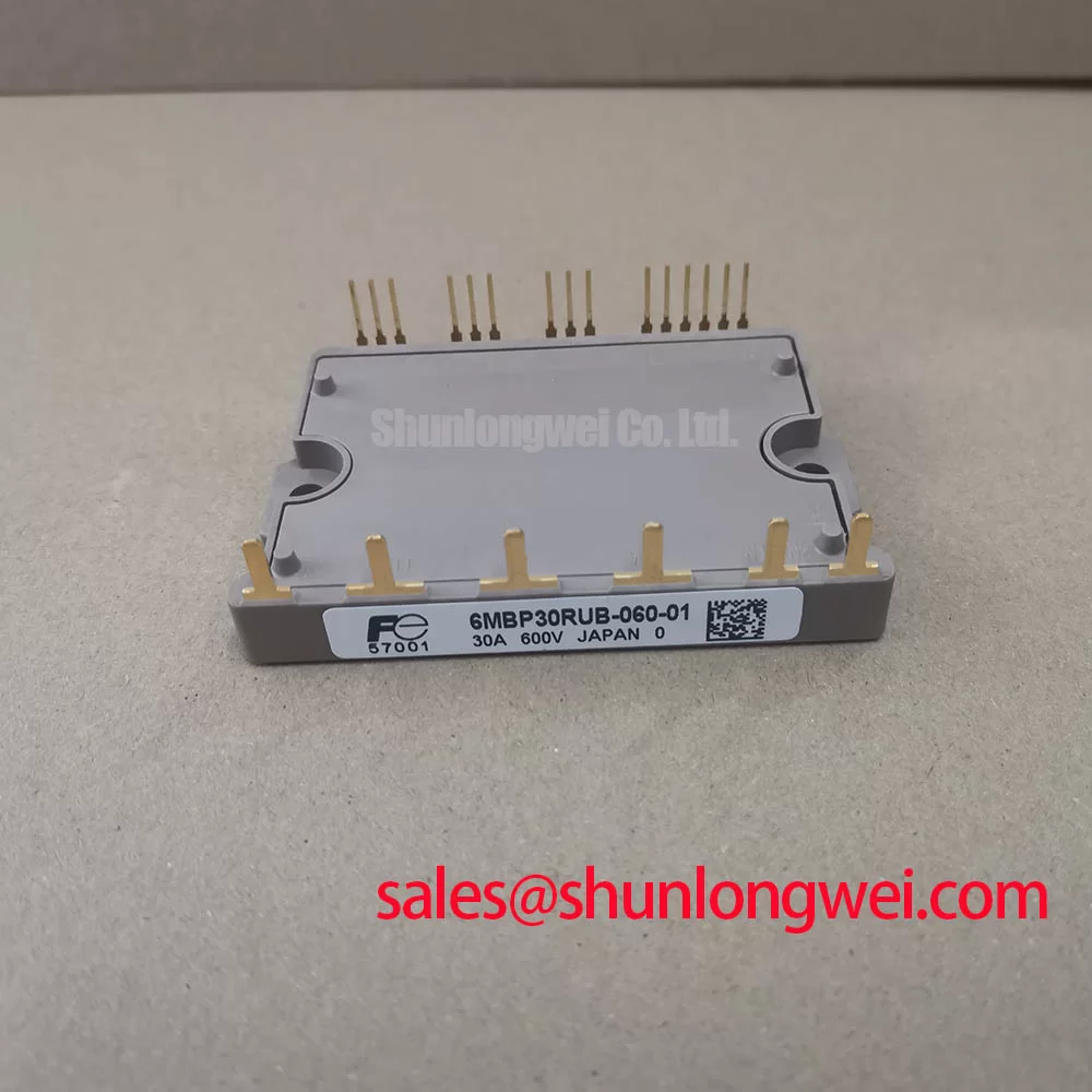
Before installing the replacement, isolate the inverter, inspect the module case and terminals, and verify the equipment nameplate against the 600 V voltage class and 30 A published current rating of the Fuji Electric 6MBP30RUB-060-01. Record the existing busbar arrangement, gate drive wiring, cooling contact condition, and terminal fastening method before removing the original device.
| Parameter | Specification | Classification |
|---|---|---|
| Manufacturer | Fuji Electric | Official product identification |
| Part number | 6MBP30RUB-060-01 | Official product identification |
| Voltage rating | 600.0 V | Published datasheet rating; operating conditions apply |
| Current rating | 30.0 A | Published datasheet rating; operating conditions apply |
| Package | Module | Official physical specification |
| Product category | IPM Module | Commercial category for product-page classification |
The stated voltage and current values identify the component’s published electrical class; they do not by themselves establish the allowable operating point in a particular inverter. Switching frequency, cooling conditions, overload profile, gate-drive behavior, motor cable construction, protection timing, and the manufacturer’s complete technical documentation remain part of the replacement assessment. Engineers should confirm the original circuit documentation before applying the module in a compact industrial inverter or high-speed CNC spindle drive.
During a replacement inspection, follow the positive and negative DC-bus paths from the bulk capacitors to the module terminals. The objective is to keep the high-current commutation loop compact, symmetrical, and mechanically stable. Laminated busbar construction can reduce the loop area between opposing conductors, while unnecessary cable length, offset plates, sharp routing changes, and loosely supported links can increase stray inductance. These are design considerations rather than published specifications for the 6MBP30RUB-060-01.
At turn-off, the voltage observed at the switching terminals is influenced by the DC-link voltage, stray inductance, and the rate of current change. In practical terms, an oscilloscope measurement should compare the switching waveform at the module terminals with the DC-link measurement point, using a properly rated differential probe and a short measurement loop. A spike that appears only at the module terminals may point toward busbar or probe-loop inductance, while a disturbance visible across the complete DC link requires wider investigation of the capacitor bank, charging circuit, snubber network, and commutation path.
Do not select a snubber capacitor solely from the 600 V label. Its voltage rating, pulse current capability, mounting inductance, damping behavior, and interaction with the switching waveform must be reviewed as part of the complete power stage. The same principle applies to an active clamp. The gate-drive designer should evaluate the Miller plateau behavior, collector-emitter overshoot, gate-loop impedance, and clamp response during double-pulse or equivalent switching tests. The required values are system-determined and should be validated against the measured peak voltage and the original Fuji Electric application documentation.
The Fuji Electric Power Semiconductor and IPM Modules resource provides a useful manufacturer reference point when checking the product family and available application information. A technically similar-looking module should not be treated as a direct substitute without confirming terminal arrangement, control characteristics, protection functions, thermal interface requirements, and mechanical dimensions.
For comparison work within the same general voltage class, engineers may review 6MBI100L-060 as a separate Fuji Electric reference device. This is a neutral comparison path, not a replacement recommendation. Any interchange decision must be based on a complete electrical, mechanical, thermal, and control-interface review.
Field Diagnostics and Commissioning for Dynamic Braking Chopper Operation
When the module is installed in a compact inverter, inspect the braking circuit as a complete energy-management path rather than testing the power module in isolation. The braking transistor, ballast resistor, DC-link capacitors, braking control signal, fuse or protective device, and discharge path all influence commissioning results. The resistor must be evaluated against the motor’s deceleration energy, duty cycle, pulse loading, enclosure temperature, and available cooling. These values cannot be inferred from the 30 A module rating.
During a controlled commissioning test, observe the DC-link voltage while the motor transitions through the intended deceleration profile. A rising link voltage can result from insufficient braking energy absorption, a control threshold problem, resistor degradation, a disconnected braking path, or an incorrectly configured drive. Confirm the actual signal at the braking control input and compare it with the known-good control sequence. Avoid assigning a single cause before checking the DC-link measurement, resistor continuity, control timing, and thermal condition.
In systems using phase-controlled rectification, the firing angle affects the average DC-link voltage and the shape of the input current. Poor coordination between the rectifier, DC-link capacitance, braking control, and motor drive can produce ripple that complicates oscilloscope interpretation. Engineers should assess line-frequency ripple, regenerative events, and braking transitions together. Harmonic mitigation may require a different front-end topology, line reactor, active rectifier, or filtering strategy; the appropriate solution depends on the complete installation and applicable site requirements.
RC snubbers can reduce ringing when their values, placement, and damping are matched to the measured switching network. An oversized capacitor can increase switching loss and stress the driver, while an unsuitable resistor can create additional pulse heating. Measure the waveform at the relevant terminals and validate the result under the actual DC-link and load conditions. The 6MBP30RUB-060-01 rating should be treated as an official component boundary, not as a complete braking-system design specification.
For a front-end or auxiliary topology review, the 6MBI15L-060 may be examined as a separate related device. Its presence in the same equipment does not establish electrical compatibility with the 6MBP30RUB-060-01. Confirm the original schematic, gate-drive requirements, protection logic, and physical layout before combining devices in one DC-link assembly.
Preventing Spurious Faults from Transmission-Line Impedance Mismatch
Long motor leads can behave as a transmission path, particularly when the inverter switching edge is fast relative to the cable propagation characteristics. Reflections at the motor terminals may increase local voltage stress, produce ringing, and create common-mode current through the motor frame or cable shield. The measured terminal waveform can therefore differ substantially from the waveform observed at the inverter output. This behavior is a system-level design consideration and is not an additional published rating of the Fuji Electric module.
For field diagnosis, inspect the motor cable length, shield termination, grounding arrangement, connector condition, and output filter configuration. Use a suitable differential probe at the inverter output and, where safe and practical, compare it with a measurement at the motor terminals. Verify that the test equipment bandwidth and grounding method do not introduce an artificial fault. A fault that appears only after the motor cable is connected may indicate an impedance or common-mode interaction, but the control board, current sensor, insulation system, and motor winding condition should also be checked.
Output chokes and dv/dt filters can alter the relationship between the inverter bridge and the motor. Their inductance, saturation behavior, capacitor current, thermal loading, and resonance must be reviewed against the drive’s switching pattern. The system integrator should select and validate these components using measured terminal voltage, motor insulation requirements, acceptable leakage current, and the equipment manufacturer’s installation limits. Avoid applying a generic filter value without checking the actual motor cable and drive configuration.
Clearance and separation around the DC bus, gate-drive conductors, current feedback wiring, and communication cables should be maintained according to the applicable equipment insulation and EMC design requirements. Keep high-current switching paths physically distinct from low-level sensing circuits, and provide firm mechanical support so vibration cannot change terminal pressure or cable geometry. The Fuji Electric 7th-Generation X-Series IGBT Modules information can provide broader manufacturer context, but it should not be used to assign unverified performance specifications to this specific part number.
Spurious overcurrent or gate-drive faults should be investigated with time-correlated measurements. Compare gate-emitter behavior, collector-emitter voltage, phase current, DC-link voltage, and fault timing. A protection trip may be associated with ringing, desaturation behavior, inadequate dead time, sensor noise, or a real load abnormality. The correct diagnosis comes from the waveform sequence and the original drive logic, not from a single voltage reading.
Transient Dynamics and Baseplate Thermal Interface Control
Remove old thermal interface material completely before fitting the replacement module. The heat-transfer surface should be clean, flat, and free from particles, hardened compound, burrs, or localized contamination. Apply only the quantity and material specified by the equipment or module documentation. The aim is to fill microscopic surface irregularities without creating a thick insulating layer. Interface thickness, compound type, mounting sequence, and baseplate flatness are installation variables that must be controlled by the system builder.
Mounting pressure should be distributed progressively across the module rather than applied abruptly at one corner. A crosswise tightening sequence is a common industry design consideration, but the actual fastener type, torque, washer arrangement, and mechanical limits must come from the relevant Fuji Electric documentation or equipment service manual. Excessive pressure can distort the baseplate or housing, while insufficient pressure can increase thermal resistance and allow movement during vibration or thermal cycling.
After commissioning, compare the module case temperature, heat-sink temperature, output current, and operating duty with the original service record where available. A gradual temperature increase may be associated with blocked airflow, fan degradation, dust accumulation, interface-material aging, uneven mounting pressure, overload, or switching loss. Inspect the complete cooling path instead of treating temperature as proof of a single failed component.
Maintenance Note: De-energize and discharge the DC link before touching the module, and periodically check heat-sink cleanliness, cooling airflow, terminal tightness, and contact temperature under a repeatable load.
For applications involving battery energy storage or bidirectional DC to DC conversion, the thermal profile should be assessed in both power-flow directions. Repeated charge and discharge transitions can produce different semiconductor and resistor heating patterns, so the engineer should record temperature rise during representative duty cycles rather than relying only on a short no-load test. Any lifetime or thermal-cycle prediction requires validated device data, mission-profile information, and an appropriate reliability method; no field-life figure is assigned here.
The negative gate-bias topic also requires system-level verification. Gate resistance, Miller coupling, driver isolation, turn-off behavior, and short-circuit protection timing should be checked against the actual schematic and waveform. The technical reference Evolution of Negative Off-Bias Gate Drive Circuits can support that review, while the final gate-drive settings remain the responsibility of the equipment designer and must be validated under controlled switching and fault tests.