

Content last revised on October 9, 2026
Preventing Spurious Faults: Mitigating Bolted Contact Oxidation and Ga Guidelines for FZ2400R12KL4C
| Manufacturer | Infineon |
|---|---|
| Product Category | IGBT Module |
| Model | FZ2400R12KL4C |
| Rated Voltage | 1200.0 V |
| Rated Current | 2400.0 A |
| Package | Module |
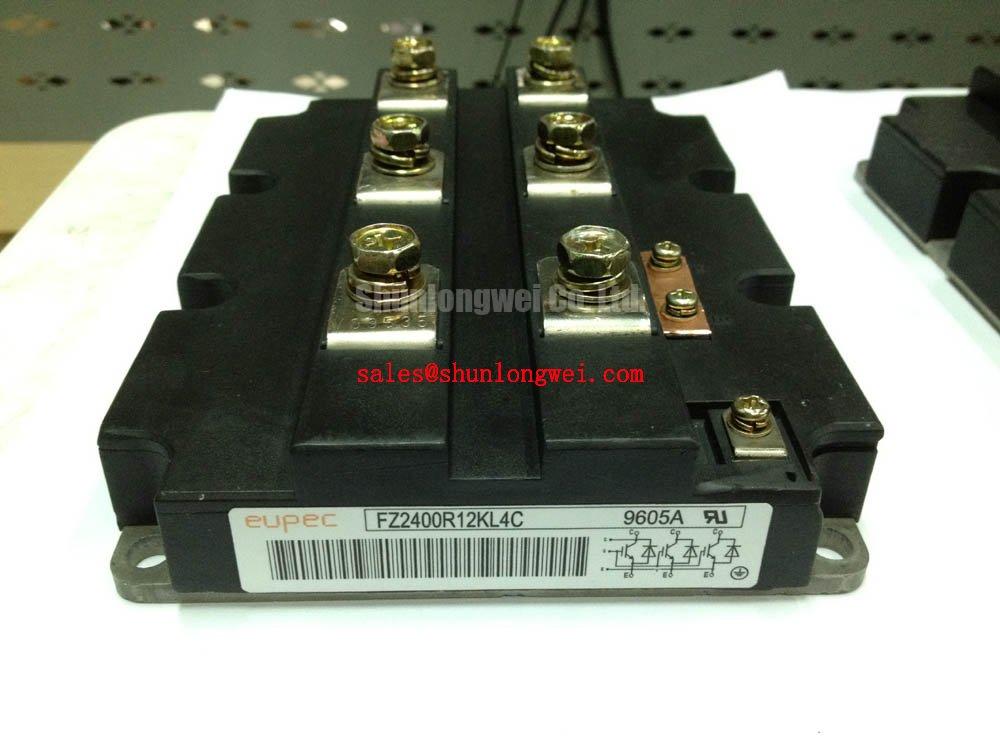
Audit each main terminal bolted joint with a calibrated micro ohmmeter before applying continuous load, then compare the measured contact pattern with thermographic images taken under controlled operating conditions. The FZ2400R12KL4C is specified as an Infineon 1200.0 V, 2400.0 A IGBT Module in a module package, so the external busbar interface deserves the same attention as the semiconductor switching circuit.
A low resistance reading at one terminal does not by itself prove that the complete connection is sound. Measure across the actual joint surfaces, inspect the clamping hardware, and repeat the check after the equipment has completed a thermal cycle. A rising contact reading, localized heating, or an uneven thermal image may point to oxidation, surface contamination, insufficient clamping, distorted busbar geometry, or cable movement. Record the phase position and operating load with every image so that later comparisons remain useful.
A contact resistance target such as less than 10 microohms may be used only when it is defined by the equipment manufacturer’s maintenance procedure or the approved connection design. It is a Design Consideration, not an automatically confirmed factory specification of this module. The system engineer should establish the acceptance limit from the terminal construction, conductor material, joint geometry, and measurement repeatability.
Keep high voltage creepage paths free from conductive dust, moisture films, and hardware that can bridge adjacent potential levels. Clearance and creepage must be checked against the complete assembly, including busbars, insulating barriers, washers, cable lugs, and enclosure contamination conditions. In offshore and onshore wind converter cabinets, condensation control and enclosure heating can be as important as the nominal insulation distance.
During troubleshooting, isolate the module and follow the site electrical safety procedure before removing any cover or terminal hardware. A contact that appears acceptable while cold can become unstable when current and thermal expansion act on the joint. Compare phase temperatures at similar load rather than judging a single image in isolation.
⚠️ Maintenance Note: Keep the heat sink and cabinet airflow path clean, and trend terminal temperature during scheduled inspections rather than waiting for an overtemperature trip.
For background on switching structures, terminal paths, and power semiconductor operating principles, consult the The Ultimate IGBT Knowledge Base. Infineon’s broader power semiconductor information, including its OptiMOS™ and CoolMOS™ Power MOSFETs portfolio, also helps distinguish device family characteristics when reviewing a complete converter bill of materials.
Transient Dynamics & Electrical Design: Dynamic Gate Impedance Control for Robust on FZ2400R12KL4C
Check the gate driver reference, emitter return, auxiliary connections, and main terminal identity against the approved mechanical drawing before connecting an energized converter. Gate loop impedance and common emitter movement can strongly affect the apparent switching waveform, especially when several high current modules operate close together.
High dv/dt can couple current into an inactive gate circuit and create unwanted turn-on behavior. A dedicated low impedance active Miller clamp is a useful Design Consideration when the driver architecture supports it. Negative gate bias is also a possible engineering measure, but its magnitude, timing, isolation rating, and driver compatibility must be determined by the system designer rather than assumed from the module voltage rating. The gate emitter voltage must remain inside the approved device and driver limits during turn-on, turn-off, fault clearing, and power-up.
Digital isolators and optocouplers should be assessed for common-mode transient immunity in the actual gate-drive environment. The relevant comparison is not only the advertised isolation voltage. Engineers should examine propagation delay matching, supply decoupling, driver return inductance, desaturation response, fault blanking, and the behavior of the isolated channel during a rapid collector-emitter transition.
Route the gate and emitter return as a controlled loop and separate high-current commutation paths from sensitive control wiring. Avoid allowing a busbar, shield, or auxiliary lead to create an unintended return path. A controlled double-pulse test or equivalent switching assessment can then be used to observe gate overshoot, false turn-on tendency, collector voltage ringing, and current sharing between parallel paths.
Vibration-proof fastening is essential in wind turbine converter cabinets. Busbar supports should prevent movement from transferring force into the module terminals, while flexible conductors should be routed so that they do not pull against the gate or auxiliary connector. Check creepage and clearance after the cabinet has been fully assembled, because a support bracket or service loop can change the shortest insulation path.
The FZ800R12KS4 may be reviewed as a separate Infineon module option during a cross-reference study, but its electrical ratings, mechanical geometry, gate-drive requirements, and thermal interface must be compared independently before any substitution decision.
Benchtop Waveform Tuning: Mitigating Stress via Main Terminal Pinout Mechanical Alignment on FZ2400R12KL4C
Align the main power terminals, busbars, washers, and cable lugs without using the fasteners to pull a misaligned assembly into position. Mechanical correction through terminal bolts can introduce bending stress into the connection system and may become more severe as the converter experiences vibration and repeated thermal expansion.
Use the manufacturer’s mechanical drawing to identify the correct terminal locations and permissible hardware arrangement. Thread engagement should be sufficient for secure fastening without bottoming the fastener or loading the terminal with an unsuitable shoulder. Washers should sit flat, and contact surfaces should be clean, parallel, and free from burrs. The selected joint method, surface finish, and tightening procedure belong to the equipment assembly specification rather than the module’s 1200.0 V and 2400.0 A nameplate ratings.
On the bench, examine the collector and emitter switching waveforms while observing the physical position of each busbar. A ringing pattern that changes when a support is touched or when a cable is repositioned can indicate a mechanical or stray inductance issue in the power path. Confirm probe bandwidth, probe ground method, and reference location before changing the gate resistor or snubber network.
Thermal cycling can expose a joint that looked correctly aligned during initial assembly. Inspect for fretting marks, washer distortion, terminal movement, and changes in the busbar plane during scheduled service. If the cabinet uses laminated busbars, maintain the intended spacing and dielectric barriers through the complete route. If it uses separate conductors, keep the commutation loop compact while preserving the required insulation distances.
Power quality at the converter input also affects semiconductor stress. A phase-controlled rectifier or active front end should be evaluated for its conduction angle, current waveform, and harmonic interaction with the grid. Harmonic mitigation belongs to the converter system and may involve control tuning, filtering, or an alternative front-end topology. It should not be inferred from the IGBT module’s rated voltage or current alone.
After mechanical alignment, repeat the low-power switching check, then increase operating conditions in controlled stages while monitoring terminal temperature, gate waveform stability, and phase current balance. Any change in waveform after cabinet transport or service should trigger a mechanical inspection before software parameters are altered.
FZ2400R12KL4C Operational Boundaries: Evaluating Antiparallel Freewheeling Diode Reverse-Recovery Limits
Evaluate the antiparallel freewheeling diode and its commutation path by observing reverse recovery current, voltage overshoot, and the rate of current change during the intended switching sequence. The reverse recovery behavior is part of the complete power loop, so the module, DC link, busbar arrangement, gate driver, load, and snubber cannot be assessed as isolated items.
A high reverse recovery peak or abrupt current transition may increase voltage stress, electromagnetic emissions, and turn-on loss in the opposing switch. An RC snubber can be considered when measured ringing exceeds the system’s verified voltage and emissions limits. Its resistor, capacitor, pulse capability, layout, and thermal behavior must be selected from measured switching energy and the converter topology. It is not appropriate to assign a universal snubber value to every installation of the FZ2400R12KL4C.
Turn-on gate resistance can also be tuned as a Typical Starting Point during controlled bench work, followed by verification of switching loss, peak voltage, reverse recovery current, gate stability, and thermal performance. The final value is system determined. A slower transition may reduce ringing while increasing switching loss, whereas a faster transition may improve loss performance while demanding tighter commutation-loop control.
Use an oscilloscope with suitable differential voltage and current probes, and compare the measured waveform at the module terminals rather than relying only on a remote DC-link measurement. Check the same operating point after the heat sink reaches its normal temperature. If reverse recovery changes with load, temperature, or control timing, document those conditions before modifying the gate network.
Fast semiconductor fuses should be coordinated with the converter’s short-circuit response and the module’s permitted fault conditions. Fuse clearing capability, available fault energy, wiring inductance, gate-driver turn-off behavior, and the fuse I²t relationship must be reviewed together. The fuse is not a substitute for desaturation protection, interlock logic, controlled dead time, or a properly tested gate-drive fault sequence.
When the module is evaluated for a multi-megawatt offshore or onshore wind turbine full-scale converter, the installation review should include grid disturbance behavior, converter isolation, cabinet humidity control, service access, and thermal monitoring. Infineon’s EasyPACK™ information can provide useful context on Infineon module families, but the electrical and mechanical limits of each product remain specific to its own documentation and system validation.