

Content last revised on October 25, 2026
FZ600R12KS4 Operational Boundaries: Preventing Internal Leadframe Cracking During Mechanical Service
- Confirm the installed device marking, 1200.0 V voltage class, and 600.0 A rated current before energizing the converter.
- Inspect main terminal thread engagement, washer seating, busbar alignment, and baseplate contact across the complete mounting surface.
- Check gate-drive isolation, power-loop routing, and the condition of the heatsink interface before commissioning.
- Record ambient conditions, cooling airflow, and any evidence of condensation or conductive dust inside the cabinet.
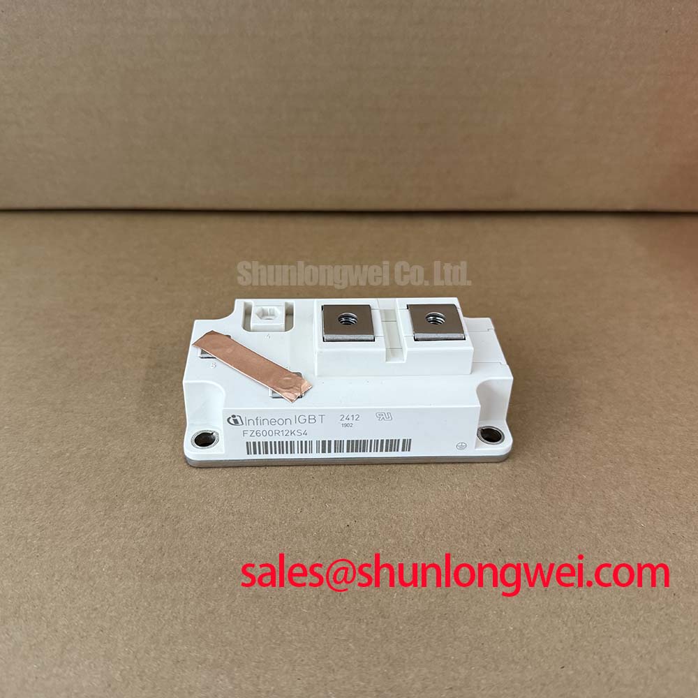
The Infineon FZ600R12KS4 is an IGBT Module specified at 1200.0 V and 600.0 A, with a module package. These are official product specifications supplied for identification and initial equipment assessment. Final operating limits remain dependent on the applicable circuit topology, switching conditions, thermal path, protection scheme, and the manufacturer’s current datasheet revision.
| Manufacturer | Infineon |
| Model | FZ600R12KS4 |
| Product category | IGBT Module |
| Rated voltage | 1200.0 V, Official Specification |
| Rated current | 600.0 A, Official Specification |
| Package | Module, Official Specification |
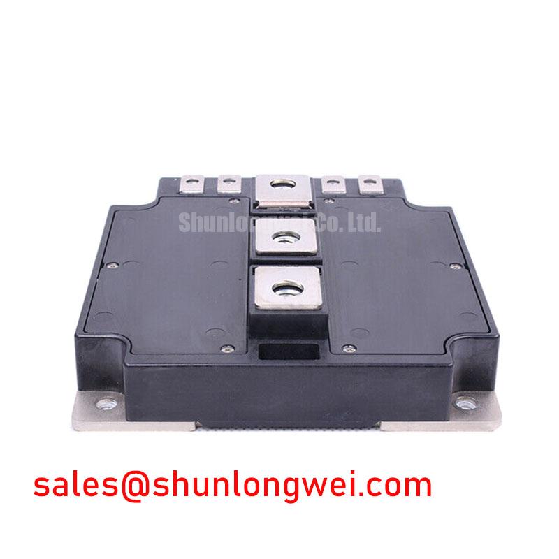
Mechanical stress at the main terminals deserves attention before electrical troubleshooting begins. A misaligned busbar, excessive washer compression, or insufficient thread engagement can transfer levering force into internal copper connections when the cabinet vibrates or the module repeatedly heats and cools. The practical objective is to keep the external connection mechanically neutral so that the terminal fastener clamps the conductor without pulling the module body sideways.
During replacement, place the module on a clean, flat heatsink surface and bring the external conductor into alignment before tightening. Do not use the terminal screw to draw a rigid busbar into position. Check that the washer bears evenly and that the conductor does not tilt as the fastener is tightened. The exact tightening torque must follow the applicable Infineon mechanical specification and the hardware grade used in the assembly. A calibrated torque tool is preferable to hand estimation.
Leave enough physical clearance for the busbar, cable lug, insulation barrier, and service tooling. Clearance is a Design Consideration rather than a fixed FZ600R12KS4 specification: it should prevent the conductor from contacting adjacent potentials and should allow thermal expansion without imposing lateral force on the terminal. After a vibration event, repeated thermal cycling, or unexplained switching noise, inspect for shifted washers, fretting marks, loosened hardware, or terminal movement. Electrical continuity alone does not prove that the internal mechanical path is healthy.
For a utility-scale central photovoltaic inverter, the module may be evaluated within a high-power switching leg, but the complete inverter must be reviewed as a system. Long DC conductors, laminated busbar geometry, gate-loop inductance, and cooling pressure all influence the stress seen during turn-on and turn-off. The Infineon IGBT Modules and Discretes Official Portfolio provides the relevant product-family context for this type of evaluation.
Field Diagnostics and Commissioning: Cosmic-Ray Robustness and Voltage Derating in FZ600R12KS4 Topologies
At elevated installation sites, terrestrial neutron exposure is a Design Consideration for high-voltage semiconductor systems, but a site altitude by itself does not establish an SEB FIT value for this module. Single-event burnout assessment requires device-specific ruggedness data, applied voltage distribution, mission profile, and an authoritative reliability method. Do not convert a generic altitude rule into a guaranteed FZ600R12KS4 failure rate.
The useful commissioning task is to document the actual peak collector-emitter stress during switching and compare it with the approved voltage boundary for the selected topology. Probe placement must avoid adding excessive loop inductance, and the measurement bandwidth should be suitable for the transient under review. If a central solar inverter operates near its upper DC-link range, the system designer should evaluate voltage headroom under cold start, regenerative events, grid disturbances, and control faults rather than relying only on the steady-state bus reading.
Gate-drive behaviour is equally important. The source and sink paths should provide controlled charging and removal of gate charge, with the external gate resistance selected as a Typical Starting Point for bench tuning rather than as a universal value. Increase damping when measured ringing threatens the gate-emitter boundary or causes unwanted turn-on; reduce it only when switching-loss and thermal results remain acceptable. The final choice is system-determined and should be verified with the installed driver, isolation arrangement, gate-loop layout, and switching waveform.
For high-altitude equipment, record the actual site elevation and operating voltage in the engineering file, then apply the reliability model required by the project owner or certification body. The Field Engineer’s Handbook can support structured testing and failure analysis without replacing device-specific qualification data.
Field Diagnostics and Commissioning: Baseplate Isolation Breakdown Testing in FZ600R12KS4 Topologies
Isolation testing should be performed with the module disconnected from the gate driver, control electronics, surge suppressors, and any parallel circuit that could be damaged by the test voltage. Any stated service audit condition, such as a minimum insulation resistance at a defined test voltage, should be treated as a project test requirement or acceptance criterion, not automatically as the module’s complete official datasheet specification unless it appears in the applicable manufacturer document.
Connect the insulation tester between the accessible power terminals and the baseplate in the test configuration defined by the equipment safety procedure. Keep the test duration, discharge method, and allowable leakage interpretation consistent across good and suspect assemblies. A changing reading can reflect surface contamination, moisture, cable capacitance, or an internal insulation problem, so the test result should be correlated with visual inspection and the isolation condition of the surrounding assembly.
Industrial airborne dust becomes more concerning when it combines with humidity and creates a conductive film along nearby surfaces. Clean the heatsink, barriers, and terminal area using an approved maintenance method, then repeat the controlled test after the assembly has reached a stable dry condition. Inspect creepage paths for deposits, tracking, damaged barriers, and compressed insulation. The required clearance is determined by working voltage, pollution environment, insulation system, and the applicable safety standard; it is not inferred from the module name alone.
Maintenance Note: Schedule periodic heatsink cleaning, inspect thermal-interface material for drying or pump-out, and trend contact temperature together with cooling-air performance.
FZ600R12KS4 Thermal-Electrical Optimization: High-Speed Semiconductor Fuse I2t Coordination
Fuse coordination begins with the complete fault path, not with the nominal 600.0 A module rating. A semiconductor fuse must interrupt the available DC-link fault energy within the time and current region supported by the IGBT assembly, while the module’s mounting structure, busbar spacing, and enclosure must withstand the resulting electromagnetic and thermal event.
Compare the fuse manufacturer’s total clearing I2t with the approved short-circuit withstand and switching protection data for the selected Infineon device. The comparison should include prospective fault current, DC-link voltage, circuit inductance, fuse temperature, parallel-path impedance, and the actual clearing characteristic. A fuse that appears suitable from its continuous current label may behave differently under a high-voltage DC fault because arc clearing and stored energy are system-dependent.
Desaturation protection, soft turn-off, gate-driver isolation, and fault reset logic should be checked as one protection sequence. The aim is to limit short-circuit energy without creating an excessive turn-off overshoot at the collector-emitter terminals. During commissioning, capture the gate signal, collector-emitter waveform, fault response, and DC-link behaviour with appropriately rated measurement equipment. Do not use the fuse as a substitute for active short-circuit protection.
In a photovoltaic inverter topology, the front-end rectification or conversion stage may be assessed alongside a complementary high-power device such as FF600R12KE4, while a neutral cross-reference for comparative engineering review is FF600R12ME4P_B11. These references do not establish automatic interchangeability. Terminal arrangement, gate-drive requirements, thermal impedance, protection thresholds, and mechanical fit must be checked at system level before any substitution decision.
Long motor or inverter cables can produce reflected-wave overshoot, and phase-controlled rectifiers can increase line harmonics when their conduction pattern is not properly managed. Bidirectional DC to DC battery systems also impose repeated thermal cycling. For each application, designers should verify transient voltage, harmonic performance, thermal cycling, fuse interruption, and gate-driver response using the final cabinet layout rather than applying a generic module-level assumption. The Infineon IGBT Modules Overview is a suitable reference point for reviewing module families and integration considerations.