



Content last revised on September 12, 2026
Constant Luminance Output Control and L70/B50 LED Lifetime Reliability Verification
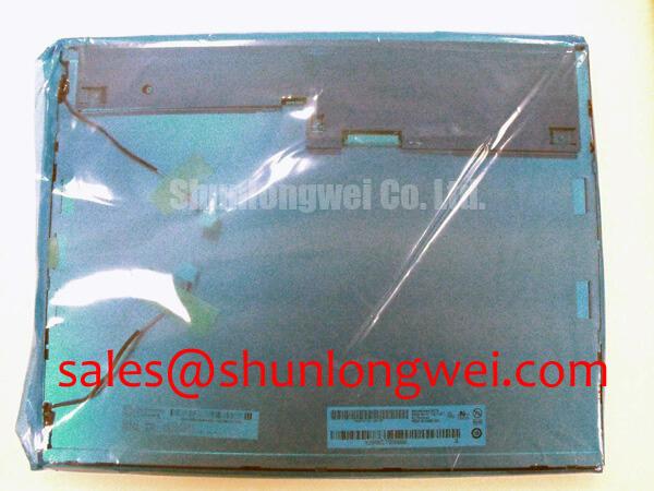
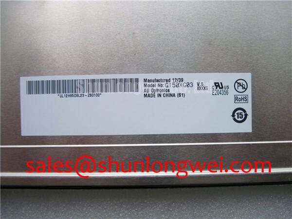
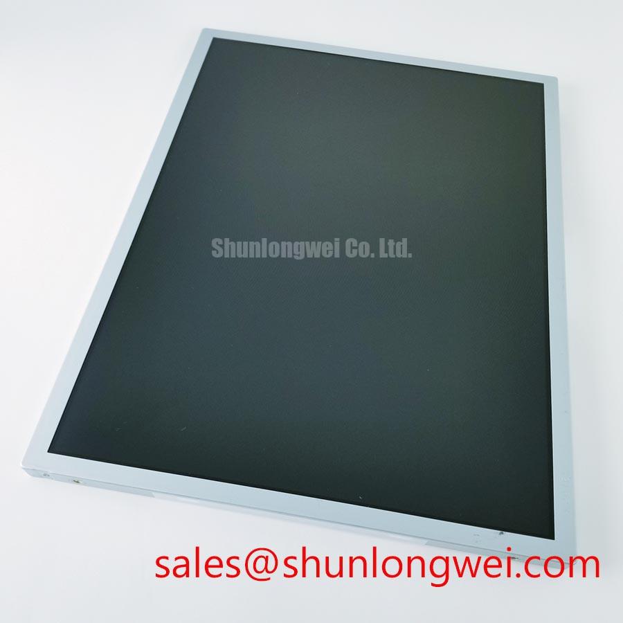
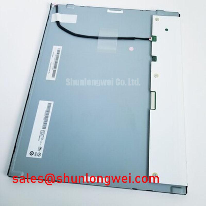
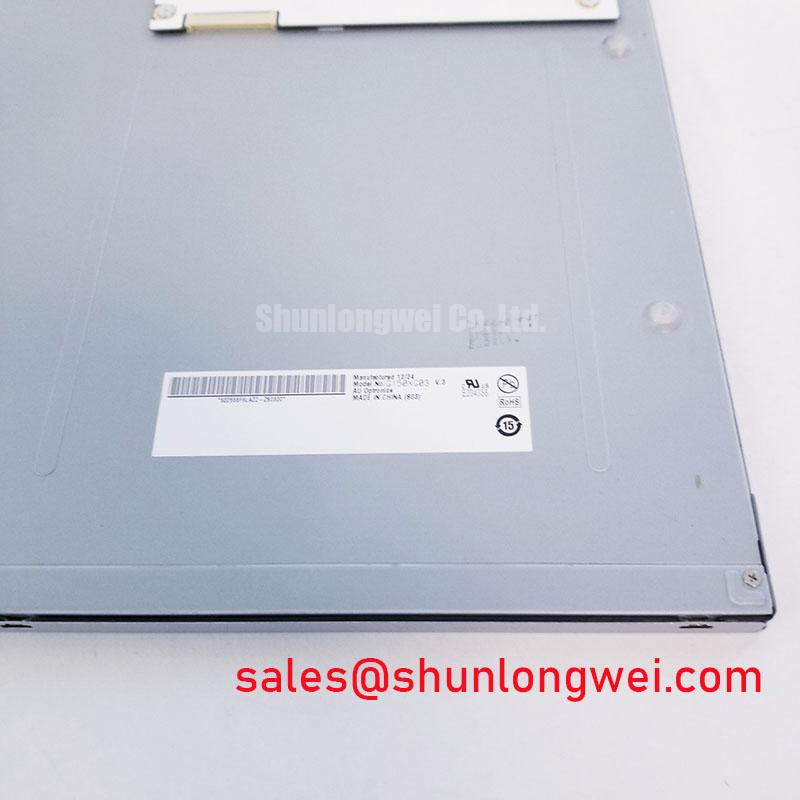
Measure the display luminance at the center and near the narrow edge zones while the panel operates in the target enclosure, then compare the pattern with the approved reference unit. This first check separates a general brightness problem from localized thermal or optical non-uniformity. The G150XG03 V3 is identified here as an AUO TFT-LCD Active Matrix Color Display Module; the supplied factory data does not establish a panel-specific L70 or B50 lifetime value, so those values must not be treated as confirmed ratings for this model.
For a replacement evaluation, record the backlight driver output, brightness command, ambient temperature, enclosure temperature, and the physical condition of the bezel interface. A gradual reduction across the entire screen points the investigation toward the driver, supply path, optical stack, or operating temperature. A bright or dim strip concentrated along one edge requires a separate inspection of mechanical compression, heat transfer, light leakage, and the mating surface around the display opening.
Aluminum heat spreader rails can be considered as part of the enclosure thermal design when the measured temperature map shows a persistent edge hot spot. This is a Design Consideration, not an AUO factory construction specification for the G150XG03 V3. The spreader must not distort the panel frame or create a hard contact point. Engineers should evaluate the thermal path together with the gasket, mounting brackets, cable clearance, and service access. The final arrangement should be validated by luminance mapping and temperature measurement under the actual duty cycle.
Backlight modulation also requires measurement rather than assumption. Use an oscilloscope or suitable photodiode measurement method to confirm the driver waveform, modulation frequency, duty-cycle response, startup behavior, and brightness linearity. A proposed PWM range such as 200 Hz to 1 kHz may be used only as a bench investigation window when supported by the external backlight driver and system requirements; it is not an official rating stated for this panel. Check for visible flicker, acoustic interaction with nearby mechanical parts, brightness stepping, and interference with camera-based inspection equipment.
L70 and B50 terminology describes defined aging and lumen-maintenance test methods. Without a manufacturer document specifying the test conditions, junction or LED temperature, drive current, sample population, and failure definition, no model-specific lifetime claim should be made. For a Zone-2 petrochemical operator station, the enclosure designer should also verify that the display assembly remains within its approved system temperature and safety envelope. The panel itself must not be presented as independently certified for hazardous-area operation.
Flashlight Dark-Shadow Optical Diagnostic to Isolate Logic and Backlight Faults
Display a known dark image, illuminate the front surface at approximately 45 degrees with a flashlight, and look for faint image content beneath a dark screen. This practical test can show whether the LCD is still forming an image while the backlight path is inactive, but it does not identify a single failed component without electrical confirmation.
Run a three-stage color check using full-screen red, green, and blue images, followed by white, black, and a mid-gray pattern. Note whether the defect follows the image content, remains fixed at one physical location, or changes when the display cable is gently stabilized without applying force to the panel. A fixed dark region may require inspection of the optical path, backlight assembly, driver connection, or panel edge. A line defect that follows the image data path requires comparison with a known-good signal and a controlled cable test.
The supplied factory data does not define the G150XG03 V3 LVDS pinout, mapping, signal amplitude, pixel clock, or differential impedance. Do not assign a connector pin function from a similar AUO panel. The system integrator should verify the original panel documentation and compare the replacement connector keying, cable orientation, power rails, enable signals, and timing sequence before applying a display signal.
For high-EMI factory cabinets, differential routing should be treated as a signal-integrity task. A 100 Ω differential characteristic impedance is a common engineering target for LVDS interconnects, but it is a Design Consideration unless the original interface documentation specifies it for this panel and cable assembly. Keep the differential pair geometry controlled through the transition from the host board to the display cable, avoid unnecessary stubs, and inspect the return path around connectors and shields. The final routing should be verified with the actual cable, connector, source device, and receiver.
Skew should be evaluated as a complete channel budget rather than assigned a universal value to the panel. Cable length, pair construction, connector geometry, source timing, receiver tolerance, and common-mode noise all affect the result. An oscilloscope or high-bandwidth differential probe can help compare clock and data arrival at the display-side connector. If the suspected fault appears only when a servo drive or switching power supply is active, correlate the screen artifact with cabinet operating states and inspect shield termination, cable separation, and bonding.
🔧 Bench Diagnostic: Disconnect power before removing or reseating the display cable, and protect the exposed connector from contamination and electrostatic discharge.
High-Humidity Storage Margins and Delamination Prevention Protocols
Inspect the perimeter seal, polarizer surface, bezel contact, and rear cable region immediately after a controlled humidity exposure, then compare the panel against a dry reference for haze, bubbles, edge lifting, image stains, and uneven brightness. These observations help distinguish moisture-related optical change from a drive-board or signal problem.
The G150XG03 V3 product information supplied for this page confirms its AUO manufacturer identity and TFT-LCD active-matrix construction, but it does not provide a model-specific 60°C and 90% RH storage qualification, delamination limit, or thermal-cycle lifetime. Those conditions may be used as a system-level environmental assessment only when they are supported by the original documentation and the complete assembly design. A test on the bare panel cannot establish the qualification of a sealed operator station.
During storage and recovery testing, allow the display to stabilize before judging image uniformity. Condensation can form when a cold panel is moved into a warm, humid enclosure, particularly around metal brackets, cable exits, and recessed front bezels. The enclosure team should evaluate venting, heater control, desiccant strategy, pressure equalization, and gasket compression as one design. The gasket must contact continuously without being over-compressed in a way that loads the glass unevenly.
Low-temperature operation can increase liquid-crystal response time and make moving graphics appear slower. This is a general LCD behavior and should not be converted into a G150XG03 V3 response-time rating without a factory data source. Use moving gray patterns and a controlled temperature chamber to observe gray-to-gray behavior across the intended operating range. Record the panel temperature, drive settings, refresh conditions, and recovery time so that the result remains useful for the complete HMI assembly.
Thermal cycling also changes the mechanical relationship between the display frame, gasket, mounting cutout, and cable. Inspect for local pressure marks and edge brightness variation after each stage. Uneven fastener loading can create optical non-uniformity that resembles a defective panel. Mounting hardware should distribute force evenly, while the enclosure designer determines the required tolerance and retention method from the panel drawing and equipment structure.
For broader enclosure decisions, engineers can refer to the practical framework in Industrial Display and HMI Solutions. It should be used as an engineering reference for environmental integration rather than as evidence of a model-specific environmental certification. If the display is considered for a hazardous petrochemical Zone-2 operator station, the station manufacturer remains responsible for the complete enclosure, temperature classification, ingress protection, wiring, and certification path.
20-Pin or 30-Pin Interface Timing, Pixel Clock, and Skew Compensation
Verify the connector count, key position, cable orientation, supply rail, display-enable behavior, and power-on waveform at the panel connector before investigating image artifacts. The supplied official hardware information does not confirm whether the G150XG03 V3 installation uses a 20-pin or 30-pin interface, so the correct connector must be established from the original equipment documentation rather than inferred from panel size or brand.
Split-screen images, shifted colors, missing columns, and unstable startup can be associated with incorrect data mapping, clock alignment, cable routing, power sequencing, or a mismatch between the host timing controller and the display receiver. Capture the host-side clock and data activity during power-up, image enable, and shutdown. Compare the waveform sequence with the known-good equipment and check whether the fault changes when the display cable is replaced with the approved cable assembly.
JEIDA and VESA mapping are not interchangeable assumptions. Confirm the color-bit assignment, lane order, clock polarity, and pixel arrangement from the original panel documentation or host-board design records. A panel can show a powered backlight while receiving an invalid data format, so brightness alone does not confirm interface compatibility. The same caution applies to logic supply voltage: the integrator should verify the required voltage from the original panel documentation instead of assuming a 3.3 V or 5.0 V input.
Power-on rise time must be checked against the actual controller, regulator, enable circuit, and cable capacitance. A proposed timing window such as 0.5 ms to 10 ms is a system verification parameter, not an official G150XG03 V3 specification in the supplied data. Measure the rail at the panel connector, not only at the power supply output, and observe overshoot, droop, sequencing between logic and backlight control, and the effect of repeated start-stop cycles.
Route LVDS pairs with a continuous reference path and keep them separated from high-current motor, relay, and inverter conductors. The 100 Ω differential target commonly used in LVDS layouts remains an engineering design consideration unless confirmed by the original interface specification. Validate the completed channel with the selected PCB stackup, connector, cable, and enclosure grounding arrangement. If the fault appears only during servo acceleration, compare the differential eye or timing margin during that event instead of relying on a static continuity test.
Ambient light testing also belongs to the complete HMI evaluation. Contrast performance under direct sunlight depends on luminance, black-level behavior, viewing angle, cover glass, surface reflection, and the enclosure window. A contrast value above 500:1 at 50,000 lux must not be attributed to this model without a supporting factory measurement. Anti-glare or anti-reflective treatment should be verified from the actual panel and cover-window configuration, since an external window can alter both reflection and image clarity.
Touch functionality should be evaluated separately from the LCD module. The supplied product facts identify the unit as an LCD display module and do not confirm an integrated resistive or capacitive touch layer, glove response, water tolerance, or touch-controller interface. If the industrial HMI requires operation with gloves or moisture present, verify the touch assembly as a complete subsystem, including its overlay, controller, sealing method, calibration, and EMC behavior.