Content last revised on September 12, 2026
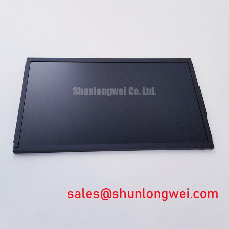
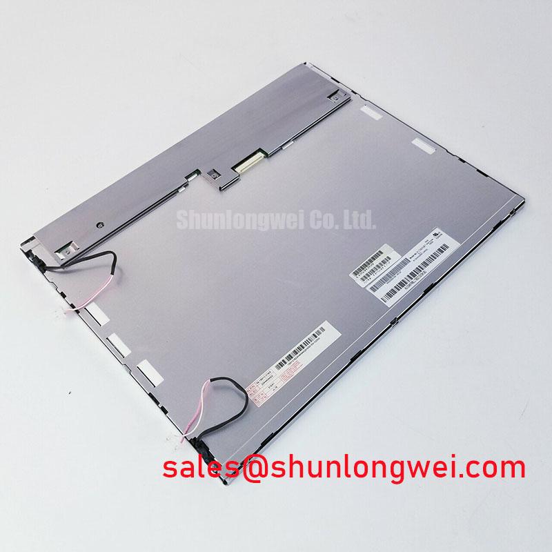
AUO G156HCE-L01 Industrial LCD Display Module
Begin a replacement assessment by checking the installed panel label against G156HCE-L01, recording the manufacturer marking, inspecting the TFT-LCD module for visible damage, and comparing the existing mounting and electrical interfaces with the original equipment documentation. The supplied factory information identifies this unit as an AUO Industrial Grade LCD/HMI Panel in a TFT-LCD Display Module package. Its specification status is listed as Official Factory Spec Verified.
This identification step matters when servicing a CNC operator panel or robot teach pendant because a display with a similar diagonal size can still differ in connector location, signal format, power requirements, backlight control, mechanical envelope, or mounting-hole position. The model number should therefore be treated as the starting point for compatibility work, not as confirmation that every visually similar panel is interchangeable.
| Parameter | Declared Information |
| Model | G156HCE-L01 |
| Manufacturer | AUO |
| Product category | Industrial Grade LCD/HMI Panel |
| Package or assembly type | TFT-LCD Display Module |
| Specification status | Official Factory Spec Verified |
The available official parameter set does not state the display diagonal, native resolution, luminance, contrast ratio, viewing angle, response time, operating temperature, connector pinout, interface standard, supply voltage, or backlight electrical limits. Those values should be taken from the original AUO panel documentation or the equipment manufacturer’s service documentation before power is applied. The system integrator should verify the required supply voltage from the original panel documentation.
For purchasing and repair records, retain photographs of the original label, connector orientation, frame, cable routing, and mounting features. These records help distinguish a correct model-level replacement from a display assembly that only appears similar during a visual inspection. The product reference and manufacturer information can be checked on the G156HCE-L01 product page.
Backlight Inverter and Ignition Debugging
Before connecting a replacement display to a CNC operator panel or robot teach pendant, identify the backlight architecture used by the original assembly. The supplied official information classifies G156HCE-L01 as a TFT-LCD Display Module, but it does not confirm whether the relevant equipment uses a CCFL inverter, an LED driver, a particular dimming method, or a specific backlight connector. Do not transfer a CCFL ignition-voltage assumption or an LED PWM setting to this model without a matching factory document.
For a field replacement, begin with the machine power isolated. Inspect the panel harness for carbonization, insulation damage, loose contacts, and evidence of mechanical strain. Confirm that the inverter or LED driver belongs to the original display architecture and that its output connector matches the replacement assembly. A display can remain dark when the image data path is healthy but the backlight system is disabled, incorrectly sequenced, or electrically incompatible.
When the original system uses a high-voltage fluorescent backlight, the service engineer should evaluate ignition behavior using equipment rated for the inverter output and follow the equipment maker’s discharge procedure. The supplied product data does not verify a cold-ignition voltage of 1500 to 1650 Vrms for G156HCE-L01, so that figure must not be treated as a product specification. The same limitation applies to claims about constant-current LED operation, 1000:1 PWM dimming, a 200 Hz to 1 kHz control range, acoustic noise, visual flicker, or a 50,000-hour life value.
A controlled bench test should separate image generation from illumination. Feed the original controller with a known-good signal path, then observe whether the panel produces a stable image under controlled ambient light. If the image is present but unevenly illuminated, inspect the backlight driver, enable signal, dimming signal, and cable seating. If the display remains blank, verify the controller output and panel interface before assigning the problem to the backlight.
Safety interlock note: Disconnect machine power and allow the original backlight circuit to discharge before removing or inserting any display cable.
Any PWM frequency, duty-cycle linearity, or ignition-voltage value used during commissioning is a system-level setting that must be confirmed against the original driver documentation and measured under the actual wiring arrangement. The G156HCE-L01 information supplied here does not establish those values as AUO specifications.
Mechanical Stress and Display-Module Inspection
Mechanical compatibility should be checked before electrical troubleshooting. Place the display on a clean, level work surface, support the frame evenly, and compare the original panel’s bezel contact points with the replacement unit. Avoid pressing the visible glass while routing the cable or securing the assembly. Localized force from a bezel, clamp, cable bend, or uneven screw loading can create a display fault that is difficult to reproduce during bench testing.
The supplied information confirms the TFT-LCD display module category but does not provide a construction drawing, glass thickness, driver-bond specification, adhesive specification, or allowable frame distortion. It is therefore not appropriate to assign a particular internal driver-bump structure, epoxy formulation, or fracture limit to this model. Inspection should remain focused on observable external conditions and documented interface requirements.
A practical three-stage bench check is to display solid red, green, and blue test fields, followed by a white field and a black field. Watch for fixed lines, intermittent columns, localized shading, color contamination, and areas that change when the cable is moved without touching the glass. These observations can help separate a signal-path problem from an illumination problem, but they do not prove a single failure mechanism. Compare the result with a known-good controller and, where possible, the original panel.
A flashlight used at an oblique angle can reveal dark regions or uneven illumination when the display is operating in a controlled environment. This is a diagnostic observation rather than a calibrated optical measurement. It may help locate a backlight distribution issue, a cable seating problem, or a visible display-area defect. The result should be correlated with the input image, driver status, and connector inspection instead of being treated as a definitive diagnosis.
Backlight lifetime and brightness decay should also be handled carefully. The available official data does not establish an LED half-life, an L70 or B50 value, or a specific 50,000-hour rating for G156HCE-L01. Those figures should only be entered into a maintenance model when they are present in the applicable AUO documentation or the backlight supplier’s qualified data. Without that source, the useful field procedure is to record brightness behavior, operating temperature, duty cycle, and driver conditions over time.
For an adjacent sourcing evaluation, engineers may review LMS700KF01-001 as a separate display product. Similar application language or a similar physical category does not establish interchangeability. Resolution, connector definition, power sequencing, mechanical dimensions, optical performance, and controller compatibility must be checked individually.
Evaluating Cold-Start Display Response
Cold-start evaluation should begin with the panel installed in its intended enclosure or on a fixture that reproduces the original cable path. Record the controller boot sequence, display enable behavior, first visible image, and any temporary image artifacts. The supplied G156HCE-L01 data does not specify a Gray-to-Gray response time, liquid-crystal operating range, cold-start delay, contrast ratio, or thermal-cycle rating, so these values should not be presented as factory characteristics.
Temperature can affect the visual response of an LCD system, but the observed delay may also involve controller initialization, signal timing, backlight enable sequencing, cable integrity, or a driver protection state. During evaluation, compare several image transitions rather than relying on one pattern. A gray ramp, moving test image, and high-contrast text screen can expose different types of temporal behavior. Use a calibrated display test method when response time is a contractual or safety-related requirement.
The equipment manufacturer’s documentation should define the required signal interface. Confirm whether the controller uses the expected LVDS or TTL arrangement, then verify lane mapping, clock polarity, data format, connector keying, and power-on order from authoritative documentation. The provided product information does not confirm a particular LVDS mapping, JEIDA or VESA format, voltage rail, enable threshold, or timing interval for G156HCE-L01. These parameters must be measured or documented before integration.
When a cold-start image appears unstable, monitor the controller’s supply rails and display control signals while comparing them with a known-good assembly. An oscilloscope can help identify timing displacement, excessive ringing, missing enable transitions, or a signal path that does not match the original installation. The diagnostic result should be expressed as a measured condition, such as an observed timing mismatch or unstable control line, rather than as an automatic conclusion about liquid-crystal material or driver-bond damage.
Direct sunlight and high ambient illumination require an optical assessment based on the actual enclosure, viewing angle, protective window, and surface treatment. The supplied official information does not verify a contrast ratio above 500:1 at 50,000 lux, an anti-glare coating, or a specific sunlight-readable luminance for this model. Designers should verify readability using the complete panel assembly and the intended user position. A display that is acceptable on an open bench may perform differently behind a protective cover or recessed bezel.
For broader service guidance on LCD interface checks, optical evaluation, and industrial installation considerations, engineers can consult The Ultimate Guide to Industrial TFT-LCD Technology. The reference can support a test plan, but it does not replace the model-specific documentation required for G156HCE-L01 integration.
Thermal Evaluation and Light-Guide Protection
Inspect the display frame, rear cover, cable exits, and surrounding heat sources before placing G156HCE-L01 into an industrial HMI enclosure. The supplied official information identifies the product as an AUO TFT-LCD Display Module, but it does not confirm a high-luminance edge-lit design, PMMA light-guide construction, aluminum heat-spreader requirements, LED rail geometry, or an L70/B50 operating-life value. Those construction and lifetime details must be verified from the applicable factory drawing or complete display specification.
Thermal assessment should cover the full assembly rather than the panel alone. Record temperatures near the backlight driver, display frame, enclosure wall, and nearby power electronics under the actual brightness and duty conditions. Check whether the enclosure restricts airflow or transfers heat into the display frame. A heat-spreading modification should only be considered after confirming that it will not distort the panel, obstruct the rear structure, interfere with the cable bend radius, or create an unintended electrical contact.
Where the original design includes an edge-mounted backlight, compare illumination uniformity at startup and after thermal stabilization. Look for localized brightness change, color shift, intermittent illumination, and visible hot areas. These observations may indicate a driver, thermal, optical, or mechanical interaction, so the next step should be correlation with measured temperature and driver status. The available product data does not support a specific allowable rail temperature or a guaranteed optical lifetime.
Designers evaluating the unit for an industrial automation CNC operator panel or robot teach pendant should verify the bezel aperture, mounting method, cable access, controller interface, power sequence, and ambient conditions as a complete system. The model identity and product category support initial sourcing, while final acceptance depends on the documented electrical and mechanical match to the equipment in service.
Design tip: Keep high-speed display signal routing separated from noisy backlight and power wiring, and verify differential-pair continuity and timing against the known-good signal path during commissioning.
Any EMC, insulation, safety, environmental, or service-life statement for the finished machine belongs to the system-level qualification record. A display module by itself should not be represented as independently certified for the completed equipment’s EMC or safety compliance.