

Content last revised on September 10, 2026
High Voltage Striking Potential and Secondary Coil Insulation Testing
When evaluating a display assembly removed from a high-voltage substation protection terminal or SCADA dispatch console, separate the LCD signal path from the backlight power path before applying any test supply. The available product identification confirms an AUO industrial TFT LCD module, but it does not confirm the panel’s original backlight architecture, ignition voltage, dimming method, supply rail, or insulation rating. Those values must be taken from the original display documentation and the equipment schematic.
CCFL backlight systems can involve a high-voltage inverter stage, while LED backlight systems normally use a controlled-current driver. These are different service conditions and must not be assumed interchangeable. If the original equipment contains a transformer-based inverter, technicians should inspect the inverter output wiring, connector insulation, and secondary-side cable routing using procedures appropriate to the host equipment. Any statement regarding ignition voltage, insulation withstand capability, PWM dimming ratio, acoustic performance, or operating lifetime requires confirmation from the applicable panel or driver specification.
Low ambient temperature can alter the apparent response of an LCD assembly and can also affect the surrounding equipment. A slow image transition, reduced contrast, or delayed backlight behavior should therefore be compared with a known-good signal source and a stable thermal condition before assigning a fault to the panel. Where the host console uses enclosure heating, heater control remains a system-level function rather than an official specification of the G156XW01 V101.
For broader context on LCD operating principles, aging mechanisms, interface selection, and practical testing boundaries, see The Ultimate Guide to Industrial TFT LCD Technology.
Chassis M3 Fastener Torque Sizing to Eliminate Optical Mura Defects
Fit the panel into the original chassis opening without forcing the bezel, twisting the display frame, or using mounting points that do not match the host enclosure. Localized mechanical stress can be associated with visible non-uniform areas, pressure marks, or image changes that become more apparent on dark or uniform test screens. Such observations require mechanical inspection and should not be treated as proof of a single internal failure mechanism.
The proposed 0.35 to 0.45 N·m range for M3 fasteners is a Design Consideration, not an official mounting requirement for the G156XW01 V101. The actual screw torque, washer stack, fastening sequence, bracket flatness, and permitted enclosure tolerance must be validated against the original panel drawing and equipment mechanical design. A cross-pattern tightening sequence can help distribute mounting load where the chassis design supports that method.
Signal stability is equally dependent on the source board and cable assembly. TTL and LVDS are distinct interface families, and the correct interface for this model must be verified from the original panel documentation. The transmitter’s clock quality, data hold timing, common reference behavior, and signal format must align with the panel requirement across the equipment’s intended operating conditions. JEIDA and VESA data mapping should never be presumed compatible without reviewing the original interface definition.
💡 Pro Tip: Disconnect all display and backlight cables only after the equipment supply is isolated, because connector damage or an incorrect reconnection sequence can create misleading display symptoms.
Full Screen Primary Color AOI Screening for Stuck Sub Pixels and Background Uniformity
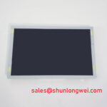
Use a stable, known-good video source to display full-screen red, green, blue, black, and white images when inspecting a removed G156XW01 V101. This bench method provides a repeatable way to observe persistent bright points, dark points, color anomalies, vertical or horizontal lines, flicker, and broad brightness variation. Record the observed pattern at the same source resolution and timing used by the host equipment whenever possible.
A practical inspection sequence begins with primary-color screens to make pixel-level anomalies easier to see. A black screen then helps reveal light leakage, uneven illumination, or intermittent noise that may not be visible on bright content. A white or neutral gray screen is useful for reviewing large-area uniformity and potential pressure-related visual changes. These checks describe visual behavior only; they do not by themselves establish whether the source is the panel, cable, timing board, backlight circuit, or host controller.
A flashlight viewed at an oblique angle can assist with locating surface contamination, bezel pressure, and external shadowing. It should be used as a visual aid rather than as a definitive diagnostic method. If a dark image remains visible under external illumination, compare the result with the expected behavior of the signal chain and the original backlight circuit. If line defects change when the cable is moved, inspect connector retention, cable strain relief, and source-board output before reaching a conclusion.
For repair documentation, keep photographs of each color screen and note whether the condition changes after cable reseating or replacement of the known-good source path. This creates a useful evidence trail for procurement and maintenance teams without presenting unsupported lifetime or reliability claims.
Shielded FFC FPC Flat Flexible Cable Grounding Across 360 Degree Connector Shells
In control cabinets located near variable-frequency motor drives, display interference can appear as image shimmer, horizontal bands, intermittent synchronization loss, or unstable color data. These symptoms can arise from several sources, including cable routing, shielding termination, ground reference conditions, source-board timing, or nearby switching equipment. The correct troubleshooting approach is to isolate one interface variable at a time and compare the display against a known-good signal path.
Where the original assembly uses a shielded FFC, FPC, or LVDS cable, preserve the original grounding arrangement and connector-shell contact method. A 360-degree shield termination is a Design Consideration for controlling cable-borne interference when the equipment’s connector system and enclosure design support it. Common-mode suppression components may also be evaluated at the system level, subject to signal-integrity testing and the host equipment’s EMC design requirements.
Differential signaling generally depends on controlled impedance, pair symmetry, and clean reference continuity. The frequently used 100 Ω ± 10% differential target and a 50 ps skew budget are system-level engineering references, not official specifications for this AUO panel. Designers should verify the applicable impedance, pair skew, clock relationship, voltage levels, and data mapping from the panel documentation and measure the installed cable path with suitable signal-integrity tools.
For a substation protection or SCADA console, route display cabling away from high-energy switching conductors where enclosure layout permits, avoid unnecessary cable length, and confirm that panel-side and controller-side connector retention is secure. If interference persists, inspect the source output with an oscilloscope against the known-good configuration and verify peak timing margins under the actual operating conditions.