


Content last revised on June 21, 2026
LTD121C33S: 12.1-inch SVGA TFT-LCD for Industrial HMI & Legacy System Integration
An Engineering-Focused Overview of the Toshiba Matsushita LTD121C33S
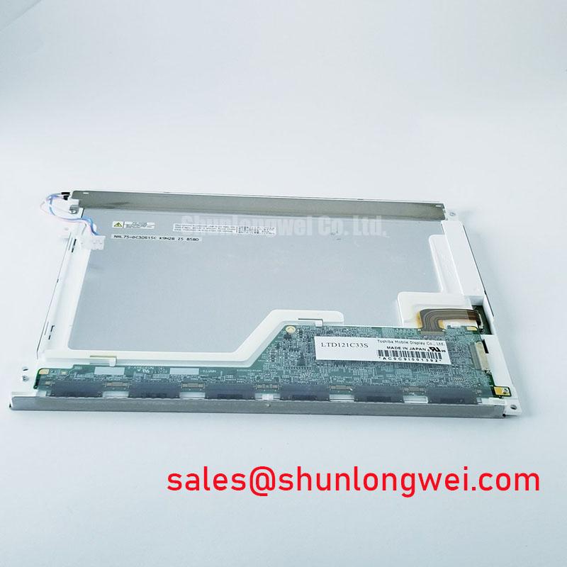
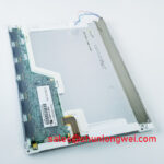
The Toshiba Matsushita LTD121C33S is a 12.1-inch a-Si TFT-LCD module engineered for stable, long-term performance in demanding industrial applications. It delivers a proven solution for system longevity and simplified integration, featuring key specifications of 12.1-inch | 800x600 SVGA | 350 cd/m² | LVDS Interface. The primary engineering benefits are its seamless backward compatibility and robust signaling integrity. For engineers tasked with maintaining or upgrading legacy industrial panels, the LTD121C33S provides a form-fit-function display that mitigates the need for extensive system redesigns by adhering to established interface and resolution standards. For industrial process control systems requiring a reliable 4:3 display, the LTD121C33S offers a proven solution for extending equipment life.
Key Parameter Overview
Decoding the Specifications for System Integration
The technical specifications of the LTD121C33S are tailored for straightforward implementation into industrial equipment. The choice of an LVDS interface is a critical design decision, offering high immunity to the electromagnetic interference (EMI) commonly found in factory environments. This ensures signal integrity over longer cable distances between the controller and the panel. Think of the LVDS connection as a secure, private communication line; unlike older, wider parallel interfaces that are like shouting across a noisy room, LVDS uses a quiet, differential signal that is far less susceptible to being drowned out by electrical noise, ensuring the image data arrives intact.
| Display Characteristics | |
|---|---|
| Panel Type | a-Si TFT-LCD, Transmissive |
| Size | 12.1 inches |
| Resolution | 800(RGB)×600, SVGA |
| Aspect Ratio | 4:3 (W:H) |
| Pixel Arrangement | RGB Vertical Stripe |
| Optical Performance | |
| Luminance | 350 cd/m² (Typ.) |
| Contrast Ratio | 500:1 (Typ.) |
| Viewing Angle | 70/70/50/70 (Typ.)(CR≥10) (L/R/U/D) |
| Display Colors | 262K (6-bit) |
| Response Time | 10/25 (Typ.)(Tr/Td) ms |
| Interface & Electrical | |
| Signal Interface | LVDS (1 ch, 6-bit), 20 pins |
| Supply Voltage | 3.3V (Typ.) |
| Backlight | 2 pcs CCFL, 50K hours lifetime (without driver) |
Application Scenarios & Value
System-Level Benefits in Lifecycle Extension and Control Applications
The LTD121C33S is engineered to solve a critical challenge in the industrial sector: the lifecycle extension of existing, field-proven equipment. Its value is most evident in scenarios where a full system redesign is economically or logistically unfeasible. What is the primary benefit of its 4:3 aspect ratio? It ensures mechanical and UI compatibility in legacy equipment.
- Industrial HMI Panels: In manufacturing and process control, many systems were designed around the 4:3 aspect ratio. The LTD121C33S serves as a direct replacement for aging or failed panels in CNC machines, PLCs, and other control interfaces, preserving the original user interface and mechanical enclosure without modification.
- Medical Diagnostic Equipment: Legacy medical carts and monitoring stations often require displays with specific resolutions and physical dimensions. This panel's SVGA resolution and standard size allow for component-level repair and refurbishment, extending the operational life of certified medical devices and avoiding costly re-certification processes.
- Test and Measurement Instruments: For specialized laboratory or field equipment, display continuity is key. The panel provides a stable platform for instruments where the software GUI is tightly coupled to the 800x600 resolution.
While the LTD121C33S is ideal for these applications, systems being designed for higher information density or outdoor use may require different specifications. For instance, new designs needing XGA resolution in a similar form factor could evaluate a panel like the G121XCE-L01.
Application Vignette
Case Study: Upgrading a Medical Imaging Display Cart
Consider a fleet of mobile diagnostic carts whose original 12.1" display has been declared end-of-life. The controlling single-board computer (SBC) outputs a standard 6-bit LVDS signal at 800x600. The primary engineering challenge is sourcing a replacement that is electrically compatible and fits the existing mounting points, crucially without requiring a new CCFL inverter design. The LTD121C33S is selected for evaluation. Its 20-pin LVDS connector is a direct match for the existing system's harness. More importantly, the datasheet confirms its backlight voltage and current requirements are within the operational range of the existing CCFL inverter. A 500:1 contrast ratio is like the dynamic range of a musical piece; for a medical imaging display presenting grayscale data, this range ensures that subtle diagnostic details are clearly visible against the background, preventing critical information from being lost in muddy, indistinct tones. The result is a successful in-house display swap, drastically reducing service costs and equipment downtime for the hospital, and demonstrating a clear total cost of ownership (TCO) advantage for legacy system support.
Frequently Asked Questions
Engineering Questions on Integration and Performance
What is the primary benefit of the standard 800x600 SVGA resolution in today's market?
Its main benefit is backward compatibility. It allows for direct, 1:1 pixel mapping in legacy Industrial HMI and medical devices originally designed for this resolution, eliminating the need for costly software redevelopment or dealing with scaling artifacts that can degrade image clarity.
Does the CCFL backlight require a specific type of driver?
Yes, it requires a dedicated CCFL inverter to generate the high AC voltage necessary for lamp operation. The datasheet specifies the required input voltage and current for the lamps, which are the most critical parameters for selecting or validating a compatible inverter to drive the backlight system effectively.
How does the LVDS interface on the LTD121C33S simplify system design compared to older parallel interfaces?
What is the key advantage of an LVDS interface? Superior noise immunity for reliable data transmission. The LVDS interface uses far fewer wires, which simplifies cable routing, reduces connector size, and lowers overall system cost. Its differential signaling provides excellent noise rejection, a critical feature in electrically noisy industrial environments, leading to a more robust and reliable video signal.
For detailed quoting or to discuss the integration of the LTD121C33S into your system, contact our engineering support team for expert guidance.