

Content last revised on June 30, 2026
LB040Q02-TD05: Robust 4.0-Inch QVGA Display for Compact HMI Systems
Introduction & Core Value
Engineered for Direct Integration and Visual Reliability
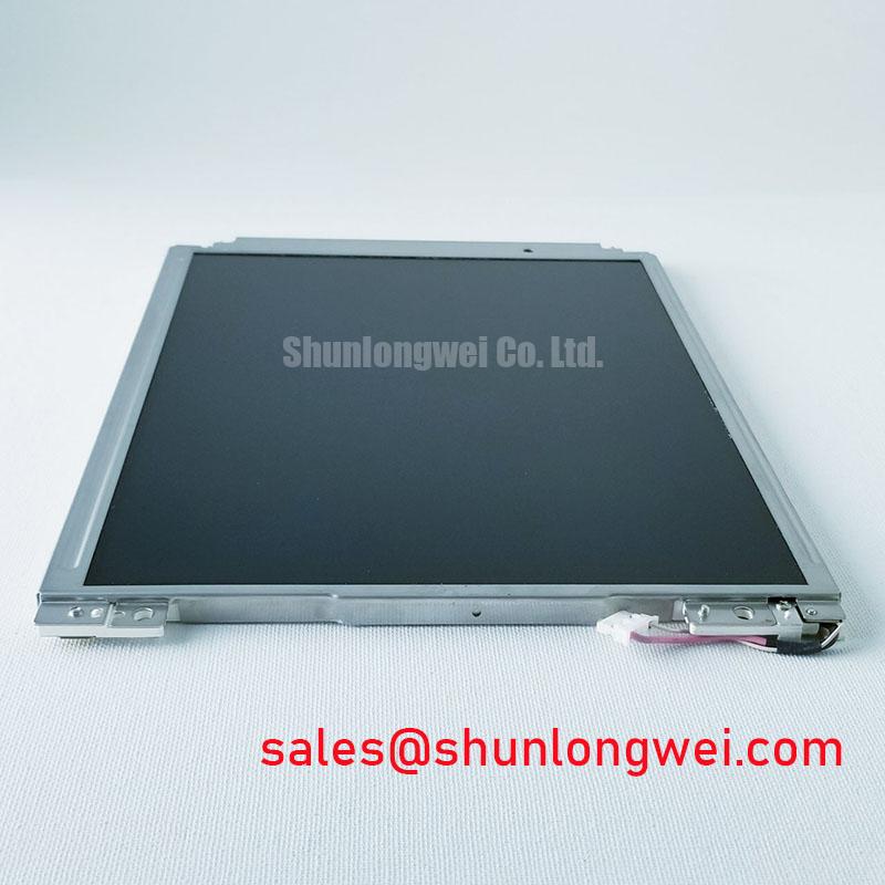
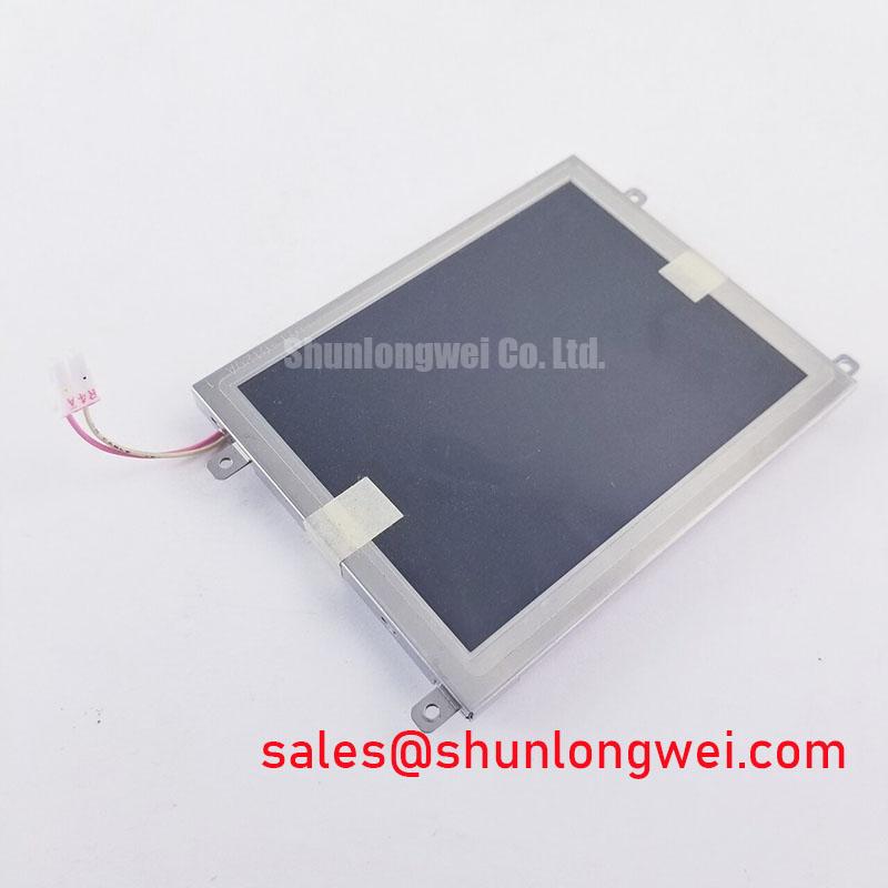
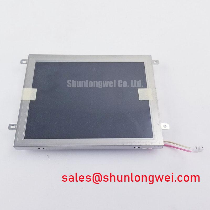
The LB040Q02-TD05 is a 4.0-inch a-Si TFT-LCD panel engineered for compact devices demanding proven performance and straightforward implementation. Its core value lies in a combination of high brightness and a direct-drive parallel interface, simplifying system architecture. With key specifications of 4.0" Diagonal | 320x240 (QVGA) Resolution | 450 cd/m² Brightness, it delivers on two critical engineering needs: excellent visual clarity in varied lighting and reduced system complexity. This display directly addresses the challenge of integrating a clear, reliable screen into space-constrained handheld and industrial equipment without requiring complex intermediary driver electronics. For portable diagnostic tools and embedded control panels where size and efficient design are paramount, the LB040Q02-TD05 provides a well-balanced solution.
Application Scenarios & Value
System-Level Benefits in Handheld and Embedded Designs
The primary engineering value of the LB040Q02-TD05 is most evident in the design of portable data terminals, environmental monitoring instruments, and handheld diagnostic tools. In these applications, engineers face the dual challenge of limited enclosure space and the need for a direct, low-latency connection to a central microcontroller. The display's parallel CMOS/TTL interface is a key enabler, creating a direct pathway for data. What is the primary benefit of its parallel interface? It streamlines the hardware design by potentially eliminating the need for a separate TCON or complex FPC, reducing both the bill of materials (BoM) and development time. This direct-drive capability, combined with a 450-nit brightness, ensures the user interface is both responsive and clearly legible, a critical factor for accurate data interpretation in the field. While the 4.0-inch diagonal is ideal for compact handhelds, for systems requiring a larger screen with similar rugged characteristics, the AA057QD01 offers a 5.7-inch alternative.
Key Parameter Overview
Decoding the Specs for System Integration
The specifications of the LB040Q02-TD05 are tailored for performance in embedded systems where reliability and visual performance are balanced against integration efficiency. The following table highlights the parameters most critical for design engineers.
| Parameter | Value | Engineering Implication |
|---|---|---|
| Screen Size | 4.0 inches | Optimal for compact and portable device form factors. |
| Resolution | 320(RGB)×240, QVGA | Provides sufficient detail for standard GUIs and data readouts without overburdening system processors. |
| Technology | a-Si TFT-LCD | A mature and reliable TFT-LCD technology known for its stability and cost-effectiveness. |
| Brightness | 450 cd/m² (Typ.) | Ensures strong readability in typical indoor and controlled outdoor lighting environments. |
| Contrast Ratio | 400:1 (Typ.) | Delivers clear differentiation between blacks and whites for sharp text and graphics. |
| Interface Type | Parallel RGB (1 ch, 6-bit) | Facilitates direct connection to a wide range of MCUs, simplifying hardware architecture. |
| Backlight | CCFL | Utilizes a conventional Cold Cathode Fluorescent Lamp for illumination. |
| Supply Voltage | 3.3V (Typ.) | Compatible with standard low-voltage logic levels found in modern embedded systems. |
Frequently Asked Questions (FAQ)
What are the primary integration benefits of the Parallel RGB interface on the LB040Q02-TD05?
The parallel interface allows for direct, high-speed data transfer from a host processor without the need for protocol conversion or complex serializer/deserializer chipsets. This simplifies the PCB layout, reduces component count, and can lower the overall system cost, which is a significant advantage for high-volume production of portable devices.
How does the 450-nit brightness impact this display's usability?
A brightness of 450 cd/m² provides strong visual performance for a wide range of indoor industrial and medical applications, as well as shaded outdoor environments. It ensures that data and graphical interfaces remain clear and legible, which is critical for minimizing user error in professional equipment. For more details on designing for ambient light, see this guide on sunlight-readable HMIs.
What is the significance of the QVGA resolution for a 4.0-inch screen?
The 320x240 QVGA resolution on a 4.0-inch diagonal screen provides a pixel density that is well-suited for displaying clear text, numerical data, and basic graphical elements. It is a resource-efficient choice that doesn't demand significant processing power or memory bandwidth, making it ideal for cost-sensitive and power-constrained embedded systems.
Is the CCFL backlight replaceable or serviceable?
The CCFL backlight is an integrated component of the display module. System designs should account for the typical operational lifetime of the backlight as specified in the official datasheet. In contrast to modern LED backlights, CCFLs generally have a more limited lifespan and may require a high-voltage inverter to operate.
Application Vignette
Deep Dive: Integration in a Handheld Environmental Sensor
Consider the engineering challenge of designing a next-generation handheld air quality monitor. The core requirements are portability (compact and lightweight), battery efficiency, and an instantly readable display for field technicians. The LB040Q02-TD05 addresses these needs directly. Its 4.0-inch form factor and typical weight of 110g allow for a small, ergonomic enclosure. More critically, its parallel interface acts like a multi-lane highway, where separate lanes carry red, green, and blue data directly from the system's MCU to the display driver. This avoids the processing "traffic jam" that can occur with serial interfaces, enabling the use of a less powerful, more energy-efficient processor.
The system-level benefit is twofold. First, the simplified hardware design accelerates the development cycle. Second, the lower power consumption extends battery life, a crucial selling point for any portable device. The display's 400:1 contrast ratio plays a vital role here. A good contrast ratio is like having a clear phone call in a quiet room; the vital information (data readings) is easily distinguished from the background, ensuring technicians can make accurate assessments at a glance, even in imperfect lighting conditions. This combination of efficient integration and clear visual output makes the LB040Q02-TD05 a strategic choice for specialized, high-reliability portable instrumentation.
Strategic Outlook
The LB040Q02-TD05 occupies a critical niche for systems that prioritize design simplicity and proven, reliable visual output over the latest high-resolution specifications. Its value proposition is anchored in providing a robust, no-frills display engine that allows engineers to build cost-effective, durable, and easy-to-integrate HMI solutions. For long-lifecycle industrial and medical products where design stability and supply chain consistency are paramount, leveraging a mature technology platform like that of the LB040Q02-TD05 remains a sound engineering strategy. It represents a commitment to functional reliability, providing the essential visual interface that connects the user to the machine with clarity and efficiency.