

Content last revised on September 10, 2026
LB121S03-TL03 Display Module Inspection and Integration
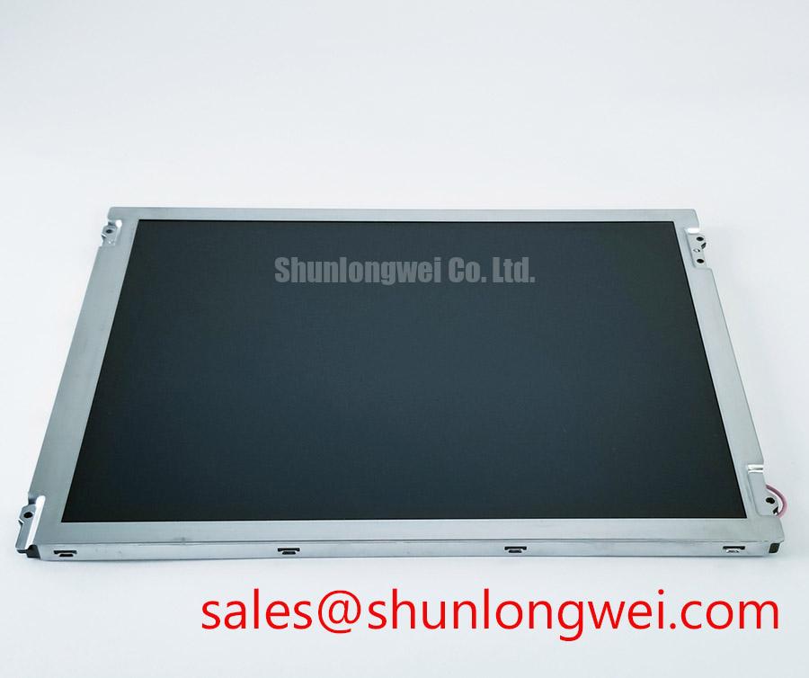
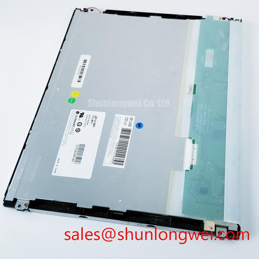
Before installing LB121S03-TL03, inspect the TFT-LCD display module for bezel distortion, connector damage, contamination, and signs of uneven mounting pressure, then compare its identification marking with the original equipment documentation.
LB121S03-TL03 is an industrial-grade LCD/HMI panel manufactured by LG Display. The available product information identifies it as a TFT-LCD display module. The supplied documentation does not confirm the panel resolution, active-area dimensions, viewing direction, interface pinout, supply voltage, backlight type, operating temperature range, or mechanical drawing. These items must be verified against the original panel datasheet and the equipment service documentation before procurement or installation.
| Model | LB121S03-TL03 |
| Manufacturer | LG Display |
| Product category | Industrial Grade LCD/HMI Panel |
| Construction designation | TFT-LCD Display Module |
| Specification status | Factory identification available; detailed specifications require verification |
| Application evaluation | Industrial HMI, monitoring panel, AGV display, and forklift telematics display, subject to system verification |
High-Voltage Striking Potential and Secondary Coil Insulation Testing
Do not treat a requested ignition voltage as a confirmed characteristic of LB121S03-TL03. The available product information does not establish whether this display uses a cold-cathode fluorescent lamp, an LED backlight, or a particular backlight driver arrangement. It also does not verify a 1500–1650 Vrms striking requirement, a constant-current LED topology, or a 1000:1 PWM dimming capability. The system integrator should verify the required backlight supply and ignition conditions from the original panel documentation before connecting a replacement inverter or driver.
For a field replacement, begin with a visual and continuity inspection of the display harness, backlight connector, inverter area, and chassis bonding points. A high-voltage insulation test should be performed only with the panel disconnected from sensitive logic electronics and only according to the original manufacturer’s test procedure. The test voltage, ramp rate, leakage-current limit, discharge time, and accessible-surface requirements are system and safety-test decisions rather than confirmed specifications for this model.
When an existing system uses a high-voltage backlight circuit, the technician should inspect for carbon tracking, cracked insulation, loose shielding, and contamination around the secondary side. Acoustic noise during ignition can result from mechanical vibration, electrical resonance, mounting contact, or an inverter operating outside its intended load range. It should not be assigned to the display module without comparing the same driver and harness with a known-good assembly.
When an LED driver is being considered, designers should verify the actual forward-voltage range, current regulation behavior, enable logic, dimming method, and protection response from the panel documentation. A replacement driver must match the optical and electrical requirements of the display rather than being selected only by connector appearance. The high-frequency current loop should be kept compact to reduce conducted noise, while the return path should be checked for common-mode voltage movement during switching.
Cold environments require a separate characterization step. Liquid-crystal response can become visibly slower as temperature falls, while an inverter or LED driver may also change its startup behavior. If an AGV or forklift display is expected to operate in sub-zero conditions, the system engineer should measure startup time, grayscale transitions, image retention, and backlight stability across the intended enclosure temperature range. Heater control, if present in the equipment, should be validated as part of the complete display assembly. No heater-strip rating or cold-start limit is confirmed here for LB121S03-TL03.
Normally White TN Grayscale Inversion Mitigation and Optimal Viewing Direction Alignment
The supplied factory data does not confirm whether this model uses a normally white TN cell, IPS technology, MVA technology, or another liquid-crystal mode. It also does not confirm a symmetric viewing specification such as 85°/85°/85°/85°. Engineers should therefore evaluate the replacement from the operator’s actual viewing position rather than assuming that a panel with a similar diagonal size will provide the same grayscale behavior.
During bench evaluation, display black, white, and mid-gray test images while viewing from the planned operator angle. Move vertically and horizontally through the expected eye position and check whether gray tones change order, wash out, or develop color shifts. This is especially relevant for forklift and AGV terminals, where the screen may be viewed from below, from the side, or through a protective window. A panel that appears acceptable directly in front of the screen may behave differently when installed in a tilted instrument enclosure.
Ambient illumination should be assessed with the intended front cover, touchscreen layer, and enclosure window in place. Surface glare can reduce contrast even when the LCD electronics are operating correctly. The available specification does not confirm an anti-glare treatment, haze value, luminance rating, or optical bonding arrangement for this model. The integrator should verify these characteristics from the original documentation and inspect the finished assembly under the actual warehouse or vehicle lighting conditions.
Backlight aging also requires careful interpretation. A stated brightness half-life, such as 50,000 hours to 50 percent brightness, must come from the applicable panel or backlight datasheet and should not be assigned to this model without a source. LED current, enclosure temperature, duty cycle, thermal paths, and driver regulation affect luminance stability. If the original system uses an external constant-current driver, record the driver’s current waveform and thermal condition during a long-duration evaluation rather than inferring backlight life from nominal operating hours.
Power and signal compatibility should be checked before any image-quality comparison. The panel supply voltage, logic levels, interface type, pixel mapping, timing, enable sequence, and backlight control signals are not included in the supplied parameters. The system integrator should verify the required supply voltage from the original panel documentation. A connector that fits mechanically does not establish electrical or timing compatibility.
For equipment with current-sense or load-monitoring circuitry near the display power path, layout review should include the measurement return path and switching-current loops. ADI’s technical material on high-precision current-sense amplifiers provides useful background on common-mode behavior and measurement placement, although it does not define the specifications of this LG Display module.
Full-Screen Primary Color AOI Screening, Stuck Sub-Pixels, and Background Uniformity Audit
A replacement display should be screened with full-screen red, green, blue, white, black, and mid-gray images before it is sealed into an industrial panel. The first check is a normal viewing inspection at the intended distance. Record any fixed bright point, dark point, line, cluster, flicker, or area with visibly different luminance. The second check uses reduced ambient light and a black image to make bright defects and edge leakage easier to observe. The third check uses white and mid-gray fields to identify broad uniformity changes that may be hidden by colorful graphics.
A fixed point visible on one color but not another may involve a sub-pixel response issue, signal timing behavior, contamination, or an upstream graphics path. Avoid assigning a single cause from appearance alone. Compare the same test pattern through the known-good signal path, inspect the cable and connector seating, and use an oscilloscope only where the equipment documentation defines safe test points. The panel’s pixel-defect acceptance criteria are not provided here, so procurement teams should obtain the applicable factory quality standard before setting pass or fail limits.
A 45-degree flashlight inspection can help separate surface contamination, cover reflections, and broad optical shadows from active-image defects. Perform the check without pressing on the panel surface. If a shadow remains stationary while the image changes, inspect the front stack, bezel contact, and backlight area. If the defect follows the image or changes with signal timing, the fault may be in the display drive path or electronics. This method is an observation aid, not proof of a particular internal failure mechanism.
Care is required when discussing COG or driver-line defects. The available product information does not confirm a particular chip-on-glass construction, bonding method, or internal fracture pattern for LB121S03-TL03. Do not apply localized pressure to the glass or edge bonds during diagnosis. Instead, document the defect location, temperature, cable position, and power state, then compare those observations with a known-good module.
For a broader explanation of TFT display operation, selection factors, and common integration errors, engineers can consult The Ultimate Guide to Industrial TFT-LCD Technology. That reference is useful for system-level evaluation, while the original LG Display documentation remains the controlling source for this model’s electrical and optical limits.
⚠️ Maintenance Note: Inspect the enclosure air path, front sealing gasket, and cable strain relief during scheduled service because dust ingress, trapped heat, or uneven gasket compression can create symptoms that resemble a display fault.
Thermal Expansion Clearance Sizing across Heavy Industrial Metal Enclosure Cutouts
Before fitting the display into an AGV or forklift telematics enclosure, compare the original mechanical drawing with the cutout, bezel support, rear clearance, connector access, and cable bend path. The available factory parameters identify the product as a TFT-LCD display module but do not provide its outer dimensions, active-area dimensions, mounting-hole pattern, bezel envelope, glass thickness, or allowable clamping load. These dimensions must be confirmed before machining or modifying the equipment chassis.
Mounting pressure should be distributed through the intended support points rather than concentrated at one corner or along an unsupported glass edge. Uneven compression can alter the optical stack and may appear as a dark patch, bright region, edge leakage, or localized mura. Such a symptom should be checked against mounting condition, enclosure flatness, gasket placement, and cable strain before the panel itself is condemned.
The requested M3 fastener torque of 0.35–0.45 N·m is not confirmed as an official mounting specification for this model. It should not be applied unless the original mechanical documentation identifies the fastener size, insert construction, washer arrangement, and permitted torque. Where the manufacturer provides no torque value, the equipment designer should establish a controlled assembly method using a suitable torque tool and verify the result through image-uniformity inspection after installation.
Thermal expansion should be treated as a clearance and support problem. The metal enclosure, gasket, display frame, protective window, and mounting brackets may not expand at the same rate. Designers should avoid creating a rigid interference fit and should verify that the display remains supported without being forced against the cutout during temperature changes. The final clearance is determined by the enclosure materials, temperature range, fastening arrangement, sealing requirements, and vibration test results.
If the display is evaluated for an outdoor-facing AGV or forklift console, condensation control deserves attention during cold starts and rapid temperature transitions. The enclosure should be reviewed for moisture paths, pressure equalization, drainage, and heater operation where applicable. No condensation rating, heater specification, vibration rating, or ingress-protection certification is confirmed for LB121S03-TL03 by the supplied product data, so these characteristics require separate equipment-level verification.
Before approving the replacement, perform a complete functional check with the production controller, intended cable routing, protective cover, and enclosure installed. Confirm image stability, backlight control, touch or keypad interaction where applicable, startup sequencing, operator viewing angle, and thermal behavior under the real system load. For a same-class comparison, engineers may review NL10276BC30-18, but substitution decisions require a documented check of dimensions, interface, optics, mounting, and electrical timing rather than a category match alone.