

Content last revised on September 10, 2026
Backlight Architecture and Secondary Insulation Testing
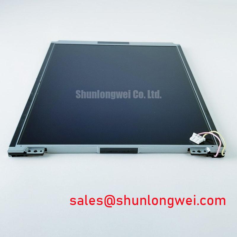
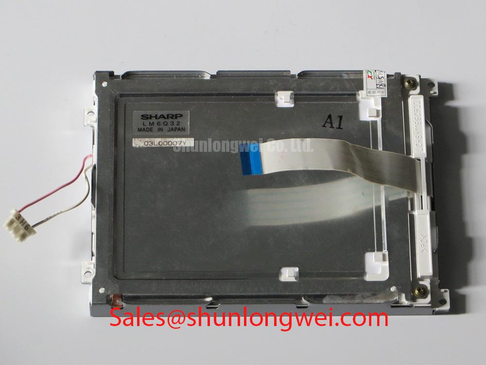
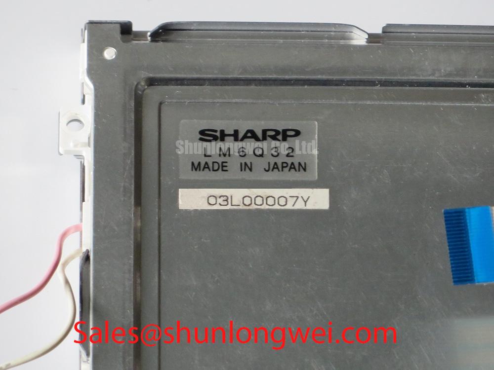
The factory information supplied for LM6Q32 does not identify its backlight technology, lamp count, driver voltage, dimming method, or electrical insulation rating. It is therefore not appropriate to assign this Sharp module a CCFL striking voltage, LED constant current requirement, PWM dimming ratio, or a service life figure. These details must come from the original panel documentation or from measurements made on the original, known working equipment under controlled conditions.
In a dark screen event, the first useful distinction is between absent image data and absent illumination. With the host equipment operating only under its approved service procedure, examine whether a stable image becomes visible under external light. A visible but unlit image can direct attention toward the illumination path, while a completely blank image requires the video interface, logic supply, and panel enable path to remain in the investigation. This is a diagnostic sequence, not a single cause determination.
Design Consideration: equipment that uses a high voltage lamp inverter requires its secondary wiring, connector insulation, and inverter enable control to be assessed as a complete assembly. Equipment that uses an LED driver instead requires review of the driver’s output behavior, protection response, and connection to the light source. Do not transfer a driver setting or a backlight test method from another display family to LM6Q32 without confirming the original hardware documentation.
Where a controller board has a transmitter stage, use an oscilloscope and a known good signal path to compare clock continuity, data activity, enable behavior, and supply stability. Excessive clock uncertainty, incomplete data settling, cable damage, or poor grounding can all affect the display result. The correct acceptance limits are determined by the specific panel interface standard and the host system design, not by the general classification of this module as a TFT LCD.
When reviewing a complete display subsystem, the related LM64P10 page can serve as a neutral reference point for comparing another industrial display solution. It should not be treated as an electrical substitute or as evidence of LM6Q32 backlight requirements.
Contrast, Optical Behavior, and Temperature Evaluation
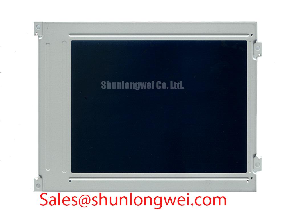
The confirmed factory information identifies LM6Q32 as a Sharp TFT LCD module, but it does not confirm the liquid crystal mode, viewing angle specification, contrast ratio, surface coating, luminance, response time, or operating temperature range. Statements assigning TN, IPS, MVA, anti glare treatment, symmetric viewing angles, or a particular contrast figure to this model would exceed the verified specification.
For field fault isolation, record what the operator actually sees from normal viewing position and from alternate angles. Gray level instability, apparent inversion, washed out dark areas, color shift, or poor sunlight readability may relate to panel optics, a mismatch in digital mapping, an unstable source image, incorrect controller configuration, or ambient reflections on the protective window. Compare the displayed test image with the output of a known good monitor where the source signal can be accessed. This helps separate content or controller issues from effects visible at the panel face.
Temperature can alter the apparent behavior of liquid crystal displays, but the expected range and permitted recovery behavior for LM6Q32 must be taken from the original Sharp documentation. Design Consideration: allow the unit to reach the equipment’s normal stabilized condition before judging response, grayscale, or uniformity. Condensation, enclosure heat retention, and airflow around the display assembly should also be evaluated because they can affect both the panel and supporting electronics.
High ambient illumination should be handled at enclosure level as well as panel level. A clean viewing window, correctly positioned shade geometry, controlled reflections, and verification of the existing optical stack can be more informative than assuming a particular anti glare or anti reflective finish. For industrial HMI and monitoring panel evaluations, the practical test is whether critical text, alarms, graphics, and cursor movement remain readable in the actual installed position.
A same class comparison should begin with mechanical drawing, active area, connector arrangement, interface type, required supply rails, and backlight integration. The LM190E08-TLG6 listing is available as a separate display reference for this comparison process. Compatibility must be verified from each model’s documentation and the original host design.
Backlight Output Control and Reliability Verification
No official factory life rating, luminance retention curve, L70 value, B50 value, or backlight mean time figure has been provided for LM6Q32. These reliability terms should not be converted into a promised operating duration for this module. Service decisions are better supported by current measurements, observed illumination stability, inspection of the driver assembly, and comparison with an approved reference system where available.
When illumination fluctuates, first inspect the panel cable and any separate illumination connector for seating, contact wear, localized heat discoloration, and strain introduced by the enclosure. Then verify that the host system reaches its intended display power state and that its backlight control signal changes in response to the operator control or system command. A driver that enters protection can produce repeated dimming or shutdown behavior, but that observation alone does not identify whether the initiating condition is the driver, load, cable, supply, or control logic.
Design Consideration: thermal control around a display should prevent concentrated heating near narrow panel edges and avoid mechanical features that place uneven force on the module. The required heat spreading method, enclosure contact arrangement, and any thermal interface material are system determined. Confirm them against the mechanical design and validate image uniformity after the equipment reaches its typical thermal condition.
If the original system documentation specifies LED illumination, inspect the constant current driver output using the maker approved test approach and ensure that open circuit and short circuit protection behavior is interpreted against that driver’s own specification. If the documentation specifies a lamp inverter, use the specified high voltage safety procedure instead. The key repair discipline is to identify the installed architecture before applying a test load, replacement board, or measurement tool.
For installations exposed to demanding ambient conditions, engineers can use the practical service and integration guidance in Industrial Display & HMI Solutions when reviewing sealing, cable retention, viewing window condition, and thermal paths. Such guidance supports a system assessment and does not establish an environmental rating for LM6Q32.
Logic Supply and Power Sequencing
The available verified data does not state whether LM6Q32 requires a particular logic supply voltage, LVDS interface, TTL interface, JEIDA mapping, VESA mapping, differential impedance, or a defined power sequencing interval. The system integrator should verify the required supply voltage from the original panel documentation. It is unsafe to infer these electrical requirements from the module’s TFT LCD classification or from connector appearance alone.
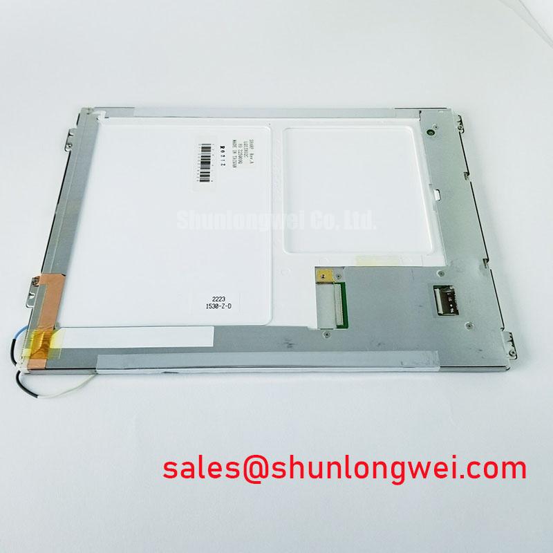
Before fitting a replacement panel, compare the original unit and candidate unit at the drawing level. Confirm the exact model marking, overall mechanical envelope, mounting point arrangement, connector position, pin assignment, interface mapping, permitted power sequence, and illumination connection. A physically compatible connector does not demonstrate signal compatibility. Incorrect bit mapping, polarity, synchronization, or enable timing can present as shifted colors, missing image sections, flicker, or an apparently failed panel.
Engineering Recommendation: control the order in which display logic power, video data, control signals, and illumination enable are applied and removed according to the original panel specification. This reduces the risk of unintended signal injection while a device is unpowered. The required timing conditions are determined by the panel, controller board, cable length, and system power architecture, and should be confirmed during switching tests on the installed equipment.
For a marine radar or navigation bridge console evaluation, treat salt exposure, direct light, vibration, enclosure sealing, and cable restraint as equipment level conditions. The LM6Q32 module can be assessed for replacement use only after its documented electrical and mechanical requirements are matched to the console’s original display assembly. Verify readability with the installed protective window, validate stable image operation through normal equipment startup, and retain the host manufacturer’s approved service limits for the final commissioning check.