Content last revised on September 10, 2026
Eye-Diagram Voltage Margin & Differential Noise Floor Verification in High-Vibration Bays
When evaluating LM150X08-TL01 in a machine display assembly, begin with the original cable path rather than applying assumptions about the signal interface. The official factory information available for this module does not confirm whether the installed system uses TTL, LVDS, or another display signaling arrangement. The system integrator should verify the required supply voltage, connector pinout, data mapping, clock relationship, and expected signal standard from the original panel documentation and the host controller schematic.
Where the original equipment uses a differential display link, an eye diagram provides a practical view of timing and voltage margin at the receiving end of the cable. Pixel jitter, intermittent horizontal bands, color sparkle, and image instability can be associated with several conditions, including cable damage, connector contact degradation, grounding discontinuity, power noise, clock integrity loss, or transmitter configuration mismatch. These observations should not be treated as a single fault diagnosis. Compare the affected signal path with a known stable channel or approved reference assembly, using measurement points that preserve the original return path.
A Design Consideration for installations near variable frequency motor drives is the continuity of shield termination around the cable entry. A shield that is terminated inconsistently can permit common mode interference to couple into the display connection, particularly where vibration gradually changes connector pressure or cable routing. A 360 degree shield termination at the enclosure entry can be evaluated when the equipment architecture supports it. Ferrite suppression can also be assessed as part of the assembled cable system, but its material selection, placement, and resulting signal impact must be verified on the operating equipment rather than selected by rule of thumb.
Clock stability and data hold time are system properties established by the source board, interconnect, receiver, and operating conditions together. When a replacement panel is considered for high precision surgical navigation or ultrasound diagnostic display equipment, technicians should verify the controller output format against the panel documentation before applying power. JEIDA and VESA data mapping, where applicable to the confirmed interface, must align with the controller output. A display can show a valid raster with incorrect color ordering when the mapping convention is not aligned.
💡 Pro Tip: Keep each differential pair routed as a controlled pair with matched physical path conditions, then confirm signal quality at the panel-side connector during actual system operation.
High vibration inspection should include the connector latch, strain relief, cable bend path, enclosure ground bond, and display frame support. Repeated motion can reveal faults that are absent during a static bench test. Observe whether image disturbance changes during controlled cable movement, provided that the equipment safety procedure permits this test. If behavior varies with movement, inspect the complete interconnect and support structure before attributing the condition to the display module.
Aluminum Heat Spreader Sizing & Thermal Interface Placement along Narrow Display Edges
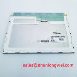
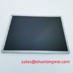
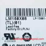
The verified product description identifies LM150X08-TL01 as a TFT LCD display module, but the available official information does not establish its thermal rating, backlight technology, optical materials, or LED lifetime specification. It would therefore be inaccurate to assign a factory operating range, claim a particular L70 or B50 operating life, or state that the module contains a defined light guide material. Such values must be taken from the original LG Display documentation for the exact panel revision.
A Design Consideration for a tightly enclosed display is to examine whether heat from nearby electronics collects along narrow display edges. Power conversion circuits, controller boards, driver assemblies, and inadequate enclosure ventilation can create local thermal gradients. An aluminum heat spreader rail can be evaluated as an enclosure level thermal measure where the mechanical stack allows it, but the rail dimensions, contact pressure, insulation requirements, and thermal interface selection are determined by the complete system. The aim is to distribute heat without twisting the display frame, loading the active optical area, or creating an unintended conductive path.
Thermal interface material should be placed only where the original mechanical design permits contact. The display’s mounting surfaces, electrical isolation requirements, and frame geometry must be verified from controlled mechanical drawings. Avoid assuming that an exposed metal area is intended as a heat transfer point. Improper contact can introduce frame stress, visible mura, edge-light nonuniformity, connector misalignment, or long-term enclosure distortion.
Cold environments require equal attention. Liquid crystal response can become slower as temperature falls, which may appear as increased gray transition lag or perceived image smear. This is a display physics consideration, not a confirmed operating characteristic of LM150X08-TL01. If the original equipment is stored or operated below normal room temperature, engineers should verify the approved operating range and response-time behavior from the original panel specification. Any heater strip, temperature sensor, or controlled warm-up arrangement must remain an equipment-level design decision with validation performed on the assembled terminal.
For backlight operation, determine whether the original system provides a regulated current source, enable signal, dimming input, open-load protection, short-circuit protection, and fault reporting. These functions belong to the confirmed panel and driver architecture; they cannot be inferred from the module category alone. During repair, inspect the driver output under controlled conditions and compare it with the original equipment service information. A no-light condition may arise from the display connection, driver protection state, cable continuity, power conversion stage, control signal state, or the light source assembly.
For broader context on panel construction, selection boundaries, and industrial display integration practices, consult The Ultimate Guide to Industrial TFT LCD Technology. That reference supports system-level evaluation but does not replace the exact documentation required for this specific module.
Single Vertical Hairline Defect & Sub-Pixel Column Driver Open-Circuit Localization
A disciplined bench inspection can distinguish a repeatable image-path defect from a backlight or viewing-angle issue without assigning an unsupported root cause. With the confirmed host interface connected and the panel operating within the original equipment conditions, display full-screen red, green, blue, white, gray, and black test fields. Observe whether a vertical line remains fixed in the same physical panel position across all relevant fields, whether it changes with cable movement, and whether it is visible only at certain brightness or contrast settings.
A practical three-stage color check begins with primary-color fields to expose channel-specific anomalies, continues with neutral gray to reveal column or row nonuniformity, and ends with black and white fields to identify light leakage, dark areas, or broad illumination variation. Record the results before reseating connectors or replacing boards. This helps separate intermittent behavior from a consistently located visual defect. A line that follows cable movement may indicate an interconnect or connector condition, while a line fixed to the same pixel column may justify further panel-level evaluation. Neither observation alone establishes the exact internal failure mechanism.
A flashlight examination at an oblique angle can help determine whether a perceived dark region is associated with the front surface, the optical stack, or loss of illumination. Use a controlled light source and avoid pressing on the panel face. Changes observed during this inspection should be compared with the full-screen test patterns. Surface contamination, protective film residue, frame pressure, backlight nonuniformity, and image data errors can create visually similar symptoms under different viewing conditions.
The official data supplied for LM150X08-TL01 does not state a PWM dimming frequency, permitted duty-cycle range, or backlight dimming method. Although PWM dimming in the general industrial range of 200 Hz to 1 kHz is often discussed during display driver evaluation, it must not be presented as an official requirement or confirmed capability of this panel. Where the original equipment uses PWM control, verify its waveform, enable sequencing, dimming polarity, and interaction with the display driver against the original service documentation. Audible noise or visible flicker can be influenced by driver topology, mechanical vibration, control waveform behavior, camera shutter interaction, and power-source stability.
For text-heavy operator interfaces, evaluate natural scrolling, fine horizontal strokes, neutral gray gradients, and low brightness settings rather than relying only on a bright white screen. This approach can reveal motion artifacts, flicker perception, or data corruption that may not appear during a short power-on check. In diagnostic display terminals, image quality should be assessed according to the equipment owner’s maintenance and clinical validation procedure. The panel itself should not be represented as carrying system-level medical, safety, or electromagnetic compliance certification unless that claim is supported by applicable equipment documentation.
Preventing Frame Lag & Image Smearing in Cryogenic Storage & Outdoor Industrial Facilities
Before approving LM150X08-TL01 for a cold-storage terminal, outdoor enclosure, or other low-temperature installation, confirm the environmental limits for the exact display revision from the original panel documentation. The verified category alone does not establish suitability for cryogenic storage, outdoor exposure, condensation, direct sunlight, high humidity, or repeated thermal cycling. Enclosure sealing, front-window construction, ventilation, cable ingress protection, and power-up control can materially affect the service behavior of the complete display assembly.
As ambient temperature decreases, liquid crystal viscosity can rise and pixel transitions can appear slower. This may be perceived as frame lag, trailing, or smearing during moving content. A Design Consideration is to evaluate the display after thermal stabilization, not immediately after equipment arrival from a colder environment. Compare the observed response with the original approved assembly using the same image content, controller settings, and brightness state. If the equipment includes temperature management, verify that its control logic and sensor feedback remain intact before replacing the display module.
Thermal cycling can also affect cable retention, gasket compression, enclosure flatness, and the panel mounting stack. Engineers should inspect perimeter support points for uneven force and confirm that no bracket, fastener, or front window applies localized pressure to the display. The required mounting hardware, torque, and clamping method must follow the original mechanical drawings; no universal torque value should be assigned to this module without confirmed factory mounting information.
Outdoor readability depends on the complete optical and enclosure system, including ambient light conditions, cover-window reflections, brightness control, and any confirmed anti-glare or anti-reflective treatment. The available factory information does not confirm AG or AR surface treatment for LM150X08-TL01. Do not specify an optical coating based on appearance alone. If the original equipment requires glare control, verify the panel surface designation and front-window stack from the original documentation before integrating a replacement.
Long-duration brightness retention must likewise be treated carefully. No authoritative lifetime curve, constant-current backlight rating, or brightness-depreciation value has been supplied for this exact module. Maintenance teams can still make an objective assessment by documenting initial luminance uniformity, checking driver fault behavior, comparing the current display against an approved reference unit, and reviewing the host system’s thermal history. This evidence-based approach supports repair decisions without converting general display-industry expectations into unsupported factory guarantees for LM150X08-TL01.