


Content last revised on September 10, 2026
High-Nits Edge-Lit LED Rail Thermal Dissipation & PMMA Light Guide Plate Preservation
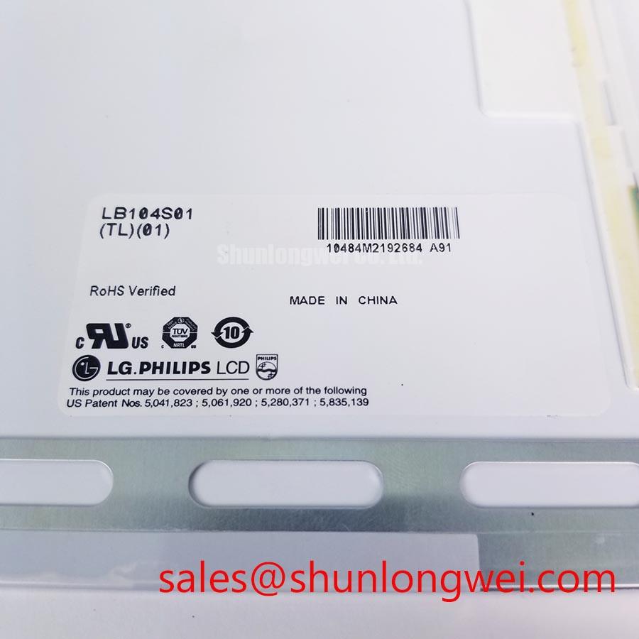
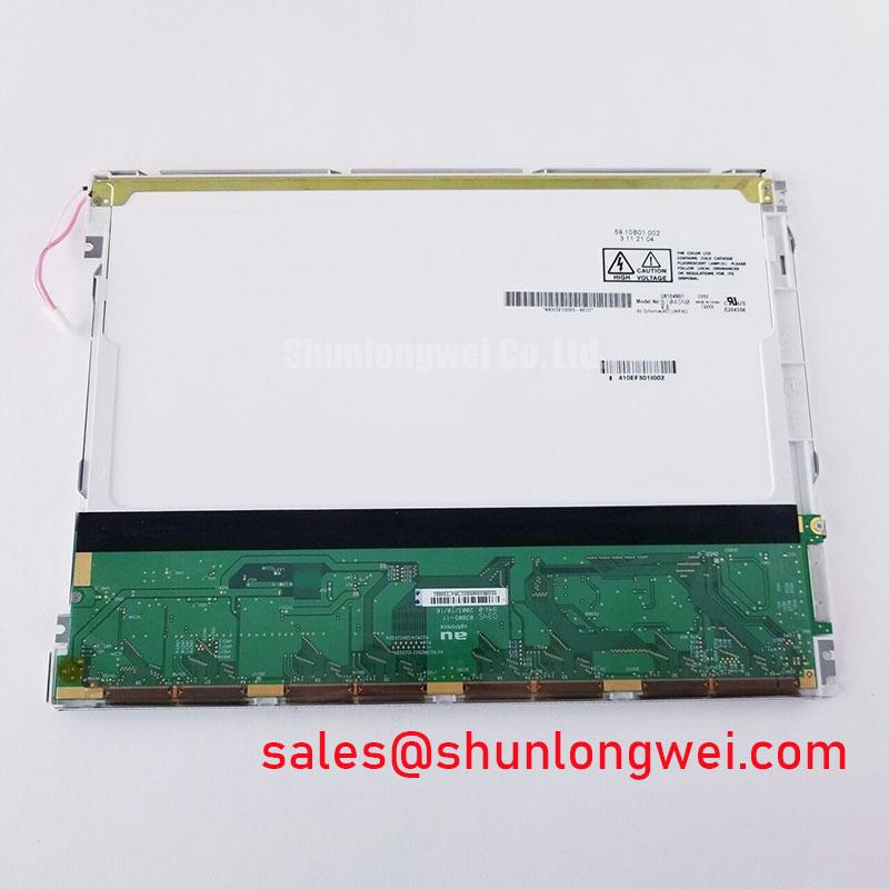
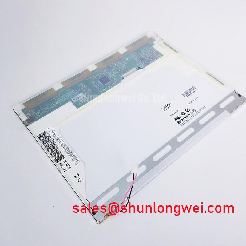
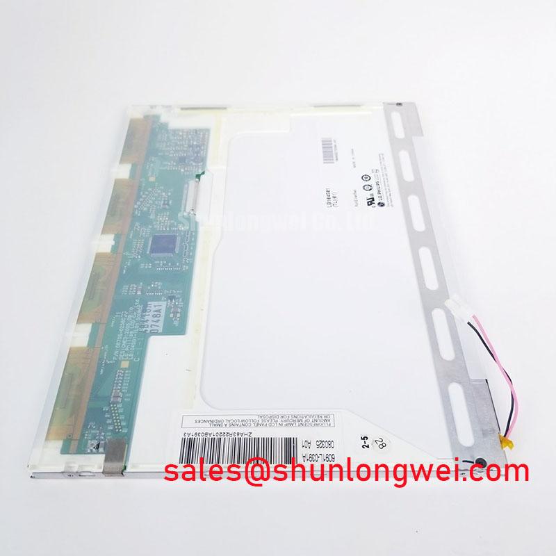
With power isolated, inspect the LB104S01-TJ02 bezel, viewing surface, connector housing, and flex-cable seating under even full-screen white, red, green, blue, and black test patterns before fitting it into an industrial HMI assembly. This LG Display TFT-LCD display module is listed as an Industrial Grade LCD/HMI Panel with Official Factory Spec Verified status. Confirm the original equipment documentation for the mating connector, input signaling, supply requirement, mechanical fit, and backlight arrangement before any replacement decision.
| Model | LB104S01-TJ02 |
| Manufacturer | LG Display |
| Product category | Industrial Grade LCD/HMI Panel |
| Module construction | TFT-LCD Display Module |
| Specification status | Official Factory Spec Verified |
During incoming inspection, compare luminance visually across the center and all four edges after the panel reaches stable operating condition. A brighter edge, localized shadow, or changing color appearance can originate in the host enclosure, rear support condition, optical stack, or backlight drive path. The official information supplied for LB104S01-TJ02 does not define a high-nits rating, an edge-lit construction, rail geometry, light-guide material, or LED lifetime target. These characteristics must not be assumed during repair planning.
As a Design Consideration, the enclosure should allow heat generated around the display and its associated illumination electronics to leave the assembly without creating concentrated hot areas along the panel perimeter. Where the original system uses a separate display controller, verify clock stability, data hold behavior, and power sequencing against the original panel documentation across the intended operating conditions. If the system documentation identifies a differential display link, inspect the cable route, connector retention, and signal quality at the known-good host path before attributing a visual issue to the panel.
💡 Bench Tip: Wear appropriate ESD protection and insert the display cable squarely and fully before locking the connector, because a skewed flex insertion can produce intermittent lines or unstable images.
Dynamic Contrast Ratio Stabilization & Liquid Crystal Birefringence Temperature Tracking
Run grayscale ramps and alternating dark-light patterns at the equipment’s expected ambient temperature, then observe whether the image remains uniform when viewed from the positions relevant to the installed terminal. Viewing angle, contrast behavior, surface treatment, and liquid-crystal mode are not included in the confirmed factory parameters provided here; no TN, IPS, MVA, anti-glare, or symmetric viewing-angle claim should be assigned to this exact module without its original LG Display documentation.
Temperature can affect perceived grayscale transitions and image response in LCD assemblies. This is an engineering observation rather than a product-specific performance guarantee. When a display is being evaluated for a passenger-information terminal or cab-signalling screen, technicians should compare it with the original unit using the same controller, cable, mounting position, and test content. For resolution terminology used in controller setup and image-source verification, consult Display Resolution Standards, while confirming the native format from the original panel record.
A visually unstable image may indicate signal-path integrity, controller timing, connector contact, or environmental influence. Check the panel with a known-good cable and compatible controller path before isolating the suspected cause. For a same-class replacement assessment, engineers can review TCG084SVLQAPNN-AN30-S, then independently validate mechanical dimensions, interface assignment, electrical requirements, and optical suitability.
Radiated Emissions Compliance via Backplate Multi-Point Star Grounding
Inspect the display cable shield termination, chassis bonding points, controller ground reference, and cable routing when horizontal bands, pixel shimmer, or image disturbance appears near motor-control equipment. The LB104S01-TJ02 is a display module, not a complete industrial machine, so it must not be represented as independently compliant with CISPR Class A or Class B emissions requirements. Compliance testing belongs to the finished equipment and its documented installation configuration.
As a Design Consideration, system designers often seek a continuous shield termination strategy and controlled return paths where high-energy switching conductors are present. The appropriate grounding topology, common-mode suppression parts, cable shield connection, and display dimming method remain system-determined and should be validated through equipment-level testing. A separately evaluated display solution such as NL10276BC30-18 can be relevant to broader service planning, but it is not evidence of electrical or mechanical interchangeability with this model.
When diagnosing visible noise, capture the supply rail and display signal at the controller with the original wiring arrangement in place. Repeating the test with the display housing bonded as installed can help distinguish a cable-routing sensitivity from a panel-level image defect.
Thermal Cycling Degradation of Polarizer Adhesives & Sealant Gasket Integrity
Before reassembly, inspect the front surface, perimeter region, rear cover, and mounting interfaces for pressure marks, contamination, moisture traces, or deformation that could alter the optical result after installation. The supplied official parameters for LB104S01-TJ02 do not confirm a specific low-to-high temperature qualification range, polarizer adhesive construction, perimeter sealant formulation, response-time value, or backlight brightness-retention life. Those figures should be obtained from the original manufacturer documentation where required by the host equipment.
Cold conditions can make LCD image transitions appear slower, while repeated environmental exposure can affect the full display assembly and surrounding seals. This is a general Design Consideration, not a declared operating guarantee for this model. For equipment requiring formal environmental evaluation, the relevant test plan should be defined by the equipment owner and assessed against applicable requirements such as MIL-STD-810 environmental engineering testing.
For installation and fault-isolation practices covering industrial TFT assemblies, see The Ultimate Guide to Industrial TFT LCD Technology. Use the original panel documentation to verify electrical sequencing and enclosure conditions before returning the repaired display system to service.