Content last revised on October 3, 2026
LM200WD4-SLB1 Replacement and Documentation Check
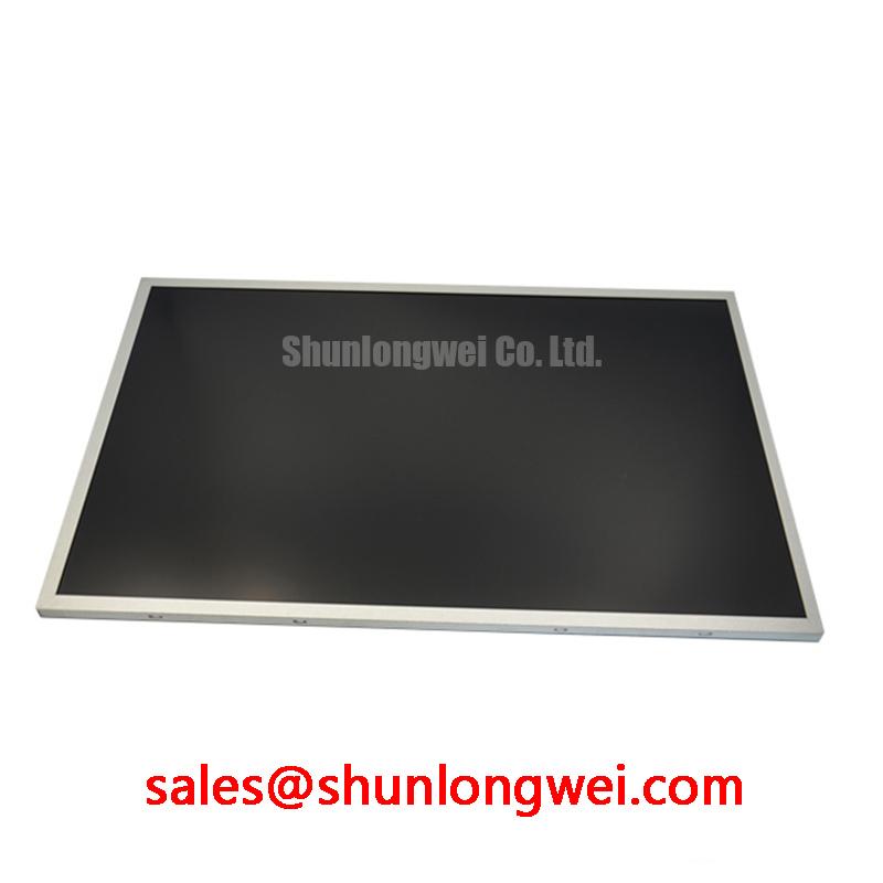
Begin a replacement check by comparing the installed panel label with LM200WD4-SLB1, then inspect the bezel, connector area, and display surface before applying power. The available factory context identifies this unit as an LG Display TFT-LCD display module in the industrial-grade LCD/HMI panel category, with an Official Factory Spec Verified status. The supplied specification record does not state a panel voltage, resolution, luminance, interface pinout, backlight current, dimensions, or operating temperature rating, so those values must be confirmed against the original panel documentation before integration.
This product page is intended for maintenance engineers and sourcing teams evaluating a display replacement in industrial operator interfaces, including potential use in heavy mining shovel and earthmoving equipment telematics displays. Mechanical fit, interface format, power sequencing, backlight control, and environmental protection remain system-level compatibility items.
| Item | Documented information |
|---|---|
| Model | LM200WD4-SLB1 |
| Manufacturer | LG Display |
| Product category | Industrial Grade LCD/HMI Panel |
| Construction category | TFT-LCD Display Module |
| Specification status | Official Factory Spec Verified |
| Interface and electrical ratings | Verify from the original panel documentation before connection |
High-Humidity Storage Margins and Delamination Prevention Protocols
Before installing LM200WD4-SLB1 in a sealed control enclosure, inspect the front polarizer, perimeter seal area, connector tail, and rear frame for signs of moisture exposure or mechanical stress. High humidity can affect the complete display assembly, but the supplied factory data does not provide a humidity storage limit, condensation rating, sealant specification, or delamination lifetime for this model. Those conditions should therefore be treated as Design Considerations, not as guaranteed characteristics of the panel.
For equipment that may remain idle in humid workshops or outdoor service vehicles, the integrator should control condensation through enclosure design, thermal management, and a suitable environmental qualification plan. Avoid sealing a cold display inside a warm, moisture-loaded enclosure without considering the temperature transition. The display should be examined after environmental exposure for haze, edge lifting, non-uniformity, connector oxidation, and intermittent image loss. These observations do not identify a single failure mechanism by themselves; they indicate that the panel, cable path, and enclosure environment require separate checks.
The requested thermal range of minus 30°C to plus 85°C must not be treated as the rated operating range of LM200WD4-SLB1 because no such rating is included in the supplied product parameters. Liquid-crystal response, optical uniformity, adhesive stability, and connector reliability can all vary with temperature. If a mining shovel or earthmoving telematics cabinet experiences rapid thermal cycling, the system engineer should validate display startup, image transition, and shutdown behavior across the actual cabinet profile.
High-speed display links also require a controlled signal path. The replacement cable should match the original connector configuration, conductor arrangement, shielding method, and data format. A differential pair that is routed beside switching nodes or motor-drive conductors may show timing disturbance or intermittent image artifacts. The practical method is to compare the suspect signal path with a known-good assembly using an oscilloscope or suitable protocol measurement equipment. The requested values of 100 ohms differential impedance and 50 ps skew are not published factory parameters for this product and should not be used as unconditional installation limits.
JEIDA or VESA pixel mapping must also be confirmed from the host controller and original panel documentation. A physically compatible connector does not guarantee correct image data alignment. If colors appear shifted, grayscale transitions are abnormal, or the image is unstable after replacement, verify pixel format, lane order, clock polarity, enable timing, and power sequencing before attributing the symptom to the LCD glass.
Flashlight Dark-Shadow Optical Diagnostic to Isolate Logic and Backlight Faults
A dark display should first be tested with the host controller operating normally and the panel connected through the original cable path. Use a controlled bench procedure: check whether the display receives its specified supply, confirm that the host is sending an active image, and then view the screen obliquely under a flashlight. A faint image beneath the illumination can indicate that image data is present while the backlight path requires further examination. It does not, by itself, prove a backlight failure, because connector contact, enable logic, protection circuitry, and panel electronics can produce similar symptoms.
For a primary-color test, display red, green, and blue fields from the host system, followed by a neutral gray field if the controller supports it. Observe the entire active area for repeating columns, horizontal bands, missing sections, unstable colors, or localized dark regions. Record whether the defect remains fixed on the glass or changes with cable movement. Do not press the panel surface or flex the frame during this test; mechanical force can create a second fault and make the result difficult to interpret.
The requested 45-degree flashlight method can be used as a practical diagnostic aid, but it is not a factory acceptance test for LM200WD4-SLB1. Similarly, no manufacturer data supplied here confirms a particular COG driver construction, anti-glare coating, optical contrast ratio, or performance under direct sunlight. A field evaluation requiring strong ambient-light readability should measure the complete display assembly with its cover glass, bezel, optical stack, and enclosure installed. A panel-level result cannot automatically represent the final HMI.
Backlight troubleshooting should follow the original electrical documentation. Verify the backlight supply requirement, enable behavior, dimming method, and current-control topology before applying an external source. The product information supplied for this page does not confirm whether the specific assembly uses a particular backlight interface, so the system integrator should verify the required supply and control signals from the original panel documentation rather than assuming a generic LED or CCFL arrangement.
When the host image is confirmed but illumination remains absent, inspect the connector, cable, backlight driver output, and protection response as separate points. When illumination is present but colored blocks or line defects remain, compare the panel input waveform and timing with a known-good unit. A single visual symptom can have several possible causes, including signal integrity, timing mismatch, connector contact, controller configuration, or panel electronics.
Thermal Expansion Clearance Sizing Across Heavy Industrial Metal Enclosure Cutouts
Before placing LM200WD4-SLB1 into a metal enclosure, use the original unit as the mechanical reference and measure the visible area, rear clearance, connector exit direction, mounting points, and bezel overlap. The supplied factory data identifies the product as a TFT-LCD display module but does not provide its outer dimensions, active area, mounting-hole pattern, bezel envelope, or fastening specification. These dimensions must be confirmed from the original drawing or a controlled sample measurement.
The enclosure cutout should support the display without transferring chassis distortion into the panel frame. A rigid metal opening that contacts the bezel at several uneven points may create pressure marks, optical non-uniformity, or difficulty during thermal expansion. This is a Design Consideration, not a documented LM200WD4-SLB1 mechanical rating. The final clearance should be determined from the manufacturer drawing, the enclosure material, the temperature profile, and the fastening method.
Use a cross-pattern fastening sequence only when the original mechanical design calls for it, and apply the torque specified by the panel or equipment manufacturer. The suggested 0.35 to 0.45 N·m range is not an official parameter supplied for this model and should not be treated as a universal limit. Excessive or uneven fastening force can distort the frame, while insufficient retention can allow vibration-related movement. The maintenance record should identify the fastener type, washer arrangement, mounting surface, and approved torque source.
⚠ Safety Interlock Note: Disconnect power before removing or inserting the display cable, and verify that the enclosure cannot re-energize during service.
For heavy equipment cabins, assess vibration transmission through the bezel and cable restraint rather than relying on the panel frame to absorb movement. The cable should have a controlled service loop and should not pull directly against the connector. If the image changes when the cable is touched, compare connector retention and signal continuity first, then inspect the host-side interface and panel input timing.
Signal routing through a metal enclosure should preserve the original differential-pair arrangement and shielding strategy. Keep display wiring separated from high-current switching conductors where practical, and verify the complete installation with the equipment operating in its normal electrical state. If a replacement panel uses a different cable length or connector orientation, the engineer should confirm the effect on signal quality instead of assuming pin compatibility from the connector shape alone.
For a same-size or same-resolution evaluation, NL192108JC18-03ND may be reviewed as a separate display option. It should not be considered a direct substitute until its active area, interface, mounting geometry, optical characteristics, power requirements, and controller compatibility have been compared with the installed LM200WD4-SLB1 assembly.
High-Nits Edge-Lit LED Rail Thermal Dissipation and Light-Guide Preservation
Do not assume a high-brightness backlight configuration, LED rail layout, PMMA light-guide construction, or L70/B50 lifetime for LM200WD4-SLB1 unless those characteristics are confirmed in the applicable manufacturer documentation. The supplied product record confirms the TFT-LCD module category but does not publish luminance, backlight technology, LED current, PWM frequency, thermal resistance, MTBF, or optical-material data.
When the original assembly uses an edge-lit backlight, the system designer should evaluate heat transfer from the display perimeter to the surrounding chassis without clamping or locally loading the panel. A spreader or mounting rail may be considered where it is compatible with the original mechanical design, but its dimensions, material, and thermal interface must be determined from measured heat generation and enclosure airflow. Adding a metal rail without checking clearance can introduce mechanical stress or obstruct the connector and cable path.
Backlight control should be matched to the original driver architecture. The requested PWM range of 200 Hz to 1 kHz is not an official LM200WD4-SLB1 specification. The integrator should confirm whether brightness is controlled by PWM, analog current regulation, a dedicated enable input, or a system-level driver. Flicker evaluation should be performed with the complete optical assembly and camera-based or photometric equipment where the application requires documented low-flicker behavior.
Backlight open-load and short-circuit protection belong to the driver and system design unless explicitly included in the panel documentation. During diagnosis, record the driver enable state, output response, current regulation behavior, and fault indication while following the equipment service procedure. Repeatedly forcing a protected output to restart can stress the driver and does not establish that the LCD module itself is defective.
For intense ambient-light applications, evaluate the installed cover, anti-glare or anti-reflective treatment, viewing angle, enclosure window, and display brightness as one optical system. No contrast ratio above 500:1 at 50,000 lux, anti-glare coating specification, or sunlight performance claim is provided for this model. These values should be measured or obtained from controlled documentation before being included in an equipment qualification statement.
The related LQ201U1LW31 can be reviewed as a separate display solution when evaluating complementary system hardware. Compatibility must be established from electrical, mechanical, optical, and controller documentation rather than from product family association alone. For broader enclosure, interface, and environmental planning, the Industrial Display and HMI Solutions engineering resource provides additional system-level context.
Before releasing LM200WD4-SLB1 for service, confirm the connector keying, panel supply, backlight control, display data format, mounting envelope, and enclosure thermal conditions against the original equipment records. These checks provide the practical basis for a controlled replacement decision without assigning undocumented electrical or environmental ratings to the module.