

Content last revised on September 11, 2026
LM32019PR Display Module Inspection and Specification Verification
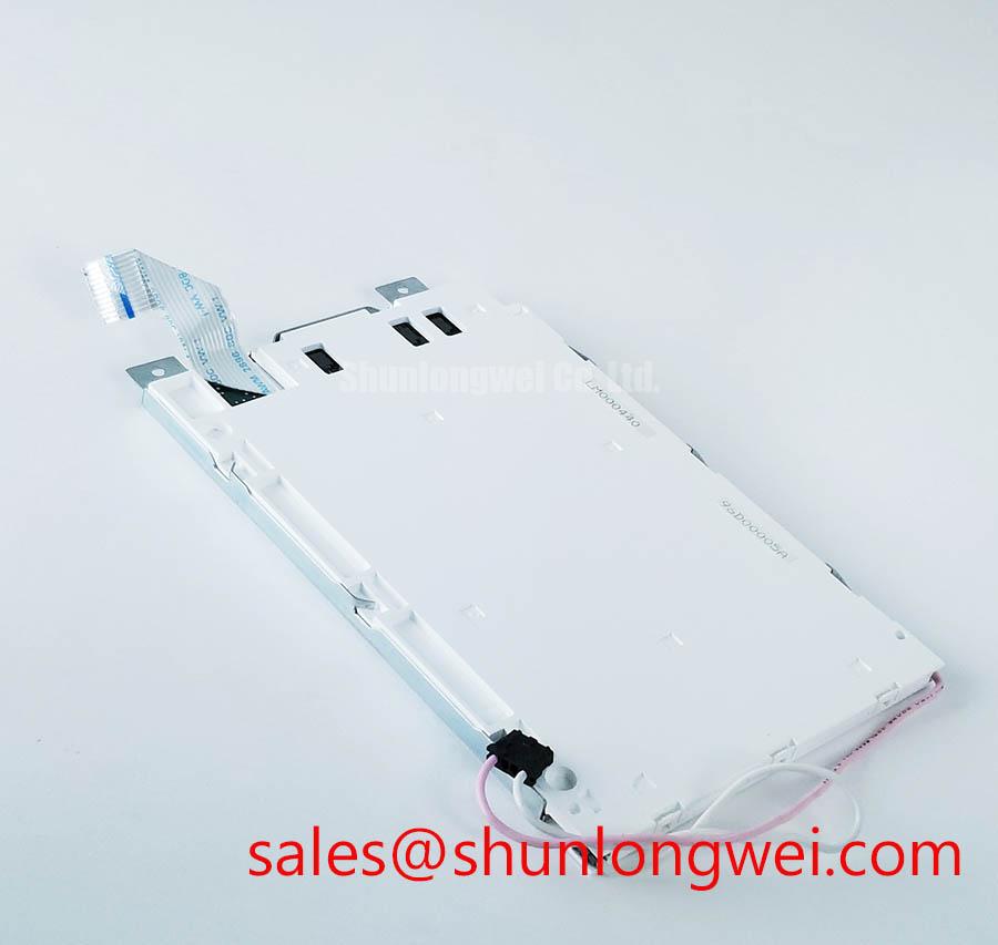
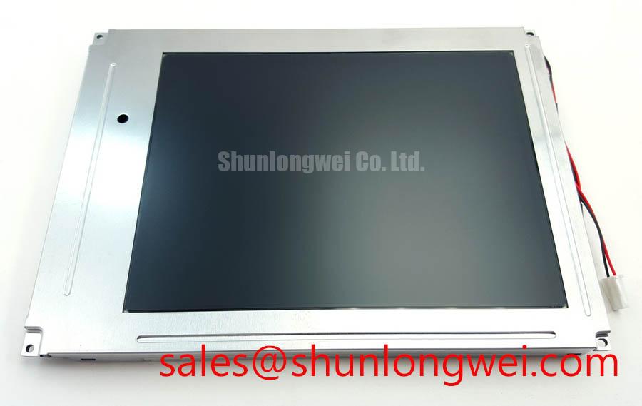
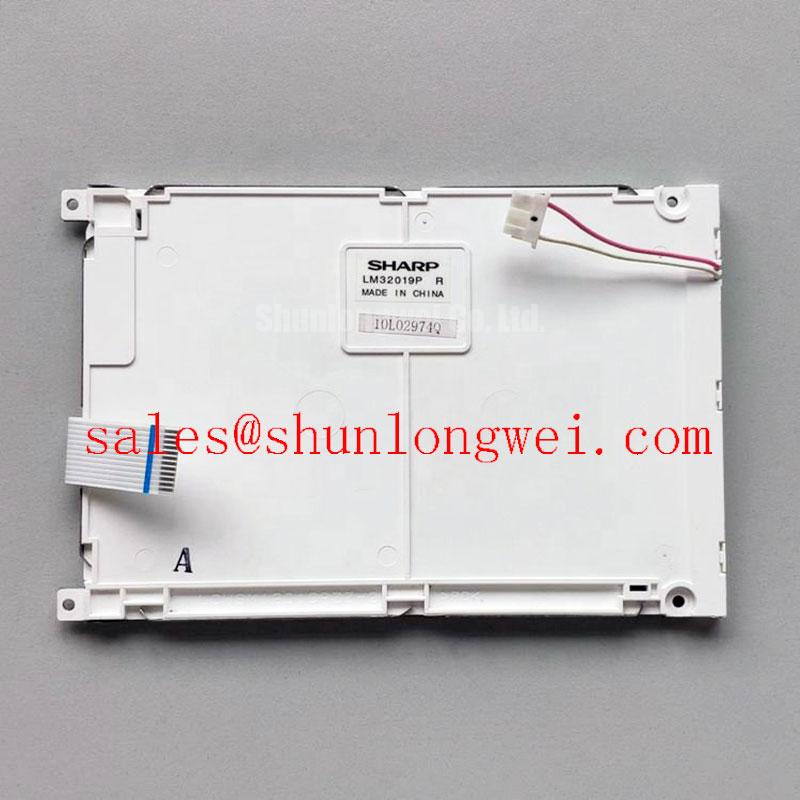
With power removed, first inspect the rear label and connector area of the LM32019PR for bent contacts, loose cable retention, contaminated terminals, bezel stress, or signs that the display assembly has been forced against its mounting frame. This initial check helps separate a panel-side concern from a host controller, cable, power rail, or backlight-driver issue before a replacement decision is made.
The LM32019PR is a Sharp industrial-grade LCD/HMI panel supplied as a TFT-LCD display module. Available factory information identifies the product category and module format, but it does not establish a pinout, native resolution, timing table, logic supply requirement, backlight architecture, optical performance figures, mounting dimensions, or environmental limits. These interface-critical details must therefore be verified from the original equipment documentation and the panel-specific datasheet before installation.
| Item | Factory Information |
|---|---|
| Model | LM32019PR |
| Manufacturer | Sharp |
| Product Category | Industrial Grade LCD/HMI Panel |
| Module Format | TFT-LCD Display Module |
| Specification Status | Available factory information is limited |
Display Interface Synchronization and Logic Power Rail Verification
Before connecting an LM32019PR replacement panel, trace the original display cable from the host board to the module connector and document connector position, keying, conductor count, shield termination, and locking method. A display that remains black, shows partial image content, or presents unstable color fields can originate from a cable seating problem, a controller-board timing fault, an incorrect panel configuration, or a logic-rail sequencing issue. The panel alone should not be assumed to be the cause.
The factory information available for this model does not confirm whether the LM32019PR uses a TTL 24-bit RGB bus, LVDS signaling, another interface format, or a particular logic voltage. Do not apply a presumed 3.3 V or 5.0 V supply based on another panel family. The system integrator should verify the required supply voltage, pin assignment, polarity, display-enable behavior, clock relationship, and power-up sequence from the original panel documentation.
Where the host system uses parallel RGB signaling, Design Consideration requires careful inspection of pixel clock, horizontal synchronization, vertical synchronization, data-enable routing, and RGB bit order. A physically matching connector does not prove that a replacement is electrically compatible. Incorrect mapping can create color inversion, repeating bands, split-screen content, shifted active area, or a blank raster even when the panel has no internal fault.
For differential display links, controlled impedance and matched pair routing are system-level requirements rather than confirmed LM32019PR factory parameters. Engineers commonly evaluate nominal 100 Ω differential impedance where the original interface is specified as LVDS, then confirm waveform quality at the receiving end against a known-good signal path. Clock instability, poor shielding continuity, damaged connector contacts, and an incorrectly seated cable may all produce intermittent image artifacts.
Timing-controller behavior also deserves attention when grayscale instability is reported. The host signal path, timing controller, and panel drive circuitry work together to translate incoming image data into pixel-level voltages. When a display shows contouring, color drift, random speckling, or unstable gray levels, compare the source output and original working configuration before classifying the panel as defective. Gamma behavior, source-board firmware, supply noise, and cable integrity can each influence the observed image.
⚠️ Field Alert: Disconnect system power and allow stored energy to discharge before removing or reconnecting the panel cable, because live connection can expose signal contacts to unintended voltage transitions.
In repair planning, replacement evaluation should begin with a side-by-side comparison of the original panel label, connector position, mechanical outline, and documented interface data. The LM190E08-TLG6 can be reviewed as a separate display-module reference for procurement comparison, but it must not be treated as a direct LM32019PR substitute without confirmed electrical, optical, mechanical, and firmware compatibility.
Backlight Drive Path Inspection and High-Voltage Isolation Boundaries
When the screen appears completely dark but a faint image can be seen under controlled external illumination, inspect the display subsystem as a chain: host power source, panel logic rail, backlight enable signal, dimming control, cable assembly, and backlight driver. This symptom can be associated with more than one fault source. A panel replacement should follow measured verification rather than assumption.
The supplied factory information does not identify the LM32019PR backlight technology. Do not presume that the module uses CCFL lamps, LED strips, a particular ignition voltage, a fixed dimming method, or a specified operating life. The system integrator should verify the backlight type, connector pinout, driver requirement, permissible dimming control, and electrical limits from the original panel documentation.
Design Consideration for systems using CCFL technology is that the inverter section can contain elevated AC voltage during startup and operation. Inspection should therefore be performed with appropriate isolation practices, suitable measurement equipment, and the equipment manufacturer’s service procedures. Secondary winding insulation, lamp harness condition, connector carbon tracking, and inverter-board deterioration can all affect illumination behavior. These checks are especially important where the display has operated for long periods in a thermally constrained enclosure.
For systems using LED backlighting, the driver is typically evaluated through its current-regulation behavior, enable response, dimming input, and connection integrity. A dim or pulsing image may be related to the driver, LED load, power supply, controller logic, or a protective shutdown condition. Verify the behavior against a known-good assembly where practical rather than interpreting one symptom as proof of a single failure mechanism.
Visual flicker and audible noise should be investigated at the system level. Dimming control implementation, switching behavior, mechanical resonance, grounding quality, and the condition of the power source can contribute to the result. If the original equipment documentation defines PWM frequency or duty-cycle requirements, those requirements should be retained during repair. No PWM frequency, dimming ratio, ignition voltage, or backlight lifetime figure is confirmed here as an official LM32019PR specification.
For high-precision surgical navigation or ultrasound diagnostic display terminals, the display module should be evaluated within the complete approved equipment assembly. Panel replacement does not establish medical-system performance, electrical safety, image accuracy, or regulatory compliance. Service teams should follow the equipment manufacturer’s validation process after any display-related repair.
Industrial Bezel Mechanical Envelope and Mounting Stress Control
Before transferring the LM32019PR into a chassis, compare the original module’s active-area alignment, rear clearance, connector exit direction, mounting-hole location, bezel contact points, and cable bend path. Mechanical mismatch can create installation problems even where a display is electrically similar. The official factory information supplied for this model does not provide dimensions, mounting-hole data, weight, thickness, or a fastening-torque specification.
Design Consideration requires the mounting frame to support the module without concentrating force on the visible display area or connector region. Uneven fastening, chassis distortion, trapped cable material, or pressure from a front window can contribute to optical nonuniformity, localized bright or dark areas, image pressure marks, or intermittent connection behavior. These effects should be assessed with the panel powered and with the enclosure assembled, because distortion can appear only after final fastening.
Use the original equipment’s mechanical drawing and service procedure to determine screw type, engagement depth, tightening pattern, and permissible torque. A cross-pattern sequence is often used as a general mounting practice when multiple fasteners are present, but it is not an official LM32019PR torque instruction. The final value must be determined by the original panel or equipment documentation and verified against the installed chassis.
Optical bonding, anti-glare treatment, viewing-angle behavior, contrast ratio, sunlight readability, and protective-window construction are not confirmed by the supplied factory parameters. Do not represent the LM32019PR as having a particular IPS, MVA, wide-angle, anti-glare, bonded, or high-brightness construction unless those details are documented for the exact unit.
Where an industrial HMI or diagnostic-display enclosure uses a front protective window, check for dust, moisture residue, adhesive contamination, and excessive perimeter pressure before installing the replacement module. The enclosure design determines sealing performance. A TFT-LCD module by itself should not be described as providing a defined ingress-protection rating or system-level environmental qualification.
For background on panel selection factors, display integration boundaries, and common industrial TFT-LCD considerations, consult The Ultimate Guide to Industrial TFT LCD Technology. The final assessment must remain specific to the original LM32019PR documentation and the host equipment configuration.
Industrial EMI Noise Immunity, Chassis Shielding Continuity and Signal-Cable Checks
When horizontal noise bands, pixel shimmer, intermittent color changes, or image dropouts occur near switching equipment, begin with cable routing and grounding inspection before replacing the display. Check whether the display cable runs alongside motor leads, inverter wiring, switching power supplies, relay bundles, or high-current conductors. Confirm that cable shields, connector shells, chassis bonding points, and strain-relief features are intact and installed as intended by the equipment manufacturer.
The available official information does not state an EMC immunity rating, shielding construction, grounding arrangement, or compliance certification for the LM32019PR. A display module should not be represented as independently compliant with complete-equipment EMC standards. Electromagnetic performance depends on the assembled product, including the host controller, cables, enclosure, grounding scheme, power supply, filtering, and surrounding electrical environment.
Design Consideration is to preserve the original cable path and shield termination where the equipment design provides them. Where the original assembly uses a shielded display harness, continuity from cable shield to the intended chassis reference should be checked carefully. A disconnected shield, loose retaining clip, oxidized grounding point, or damaged cable braid can permit noise coupling into sensitive display signaling.
Common-mode filtering is also a system-level choice. If ferrite components are present on the original harness, inspect their placement and physical condition rather than relocating or removing them during repair. Any added suppression component should be validated by the system engineer because it can affect signal integrity, cable loading, and the behavior of the complete equipment.
For an intermittent issue, compare operation with the original cable and a verified cable assembly, observe the display while nearby loads cycle, and inspect the host-side supply rails under normal operating conditions. This approach helps distinguish panel faults from interference, power instability, controller malfunction, or harness damage without assigning a single cause to every visible artifact.