



Content last revised on October 15, 2026
Cleaning Zebra Rubber Strips and PCB Gold Contact Pads with Anhydrous Isopropyl Alcohol (IPA)
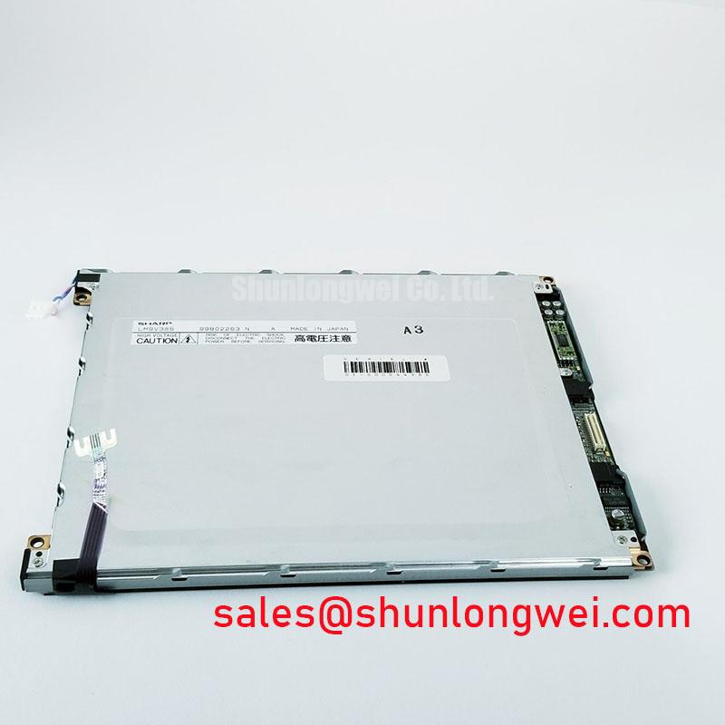
With the precision test instrument powered down, inspect the LM9V385 bezel, flex connection, and contact area before applying cleaning fluid or attempting an inverter adjustment. For the Sharp LM9V385 LCD panel, operating voltage, pin assignment, backlight type, and timing limits must be matched to the original equipment documentation before installation.
For field replacement work, treat the panel as the display element rather than assuming that the host instrument uses a particular supply rail, backlight circuit, or digital interface. Precision electronic test and measurement instruments can expose a display to vibration, repeated thermal cycling, and long periods of static text. A compatible replacement therefore requires mechanical alignment, contact pressure, contrast adjustment, backlight compatibility, and signal timing to be checked as one system.
If the display assembly uses an elastomeric zebra connector, missing rows or columns often require attention at the connector and PCB gold contact interface before the LCD itself is condemned. Remove power, release the bezel without twisting the glass, and lift the zebra strip in its original orientation. Use anhydrous isopropyl alcohol on a lint-free swab for the PCB contact pads, allowing the surface to dry completely before reassembly. Avoid flooding the elastomer, flex tail, or edge seal.
The zebra strip must sit squarely across the full contact width. A small lateral displacement can interrupt selected rows or columns while leaving the rest of the image apparently normal. Clean the retaining channel, check for foreign particles, and reinstall the strip without stretching it. The bezel should apply even mechanical compression across the display edge. The required compression depends on the connector specification, bezel geometry, elastomer condition, glass thickness, and PCB support.
After reassembly, display a full character pattern and then a checkerboard or alternating line pattern. A fault that moves with the zebra strip points toward alignment or contact compression. A fault that remains fixed should be compared with the controller output and the corresponding PCB trace. Do not scrape the gold pads, because removing the contact finish can create a permanent intermittent connection.
If the host assembly uses a cold cathode fluorescent lamp, keep the inverter and lamp wiring physically separated from the exposed LCD contact area. Ignition pulses in a CCFL system are hazardous high voltage and can promote corona or arcing when insulation, creepage, transformer potting, or ballast routing has deteriorated. The ignition and sustained-current values belong to the inverter and lamp assembly documentation, not to the passive LCD panel specification. Sharp display information can be cross-checked through the Sharp Display Solutions Official Portal.
CCFL Inverter Strike Failure Localization: Differential Tube Aging vs. Ballast Transistor Breakdown
When the instrument powers up with a dim, flickering, or completely dark screen, first separate the display data path from the backlight path. Shine a controlled external light across the panel while the instrument is operating and look for a faint image. A visible image indicates that the LCD drive may be active while the illumination circuit requires investigation; no visible image requires examination of power, control signals, connector seating, and panel contrast as well.
For systems fitted with CCFL illumination, compare the inverter behavior with a known-good lamp or approved test load. A lamp that starts slowly, changes brightness, or extinguishes after ignition can produce symptoms similar to a failing ballast transistor. Inspect the transformer body, lamp sockets, wiring insulation, and PCB for carbon tracking or heat discoloration. Measure only with probes and instruments rated for the inverter output, using the clearance and insulation requirements specified by the original equipment manufacturer.
Ballast transistor breakdown may be accompanied by abnormal switching waveform shape, excessive supply loading, or repeated protection shutdown. Tube aging may instead appear as unstable striking, uneven brightness, or a change in behavior after warm-up. These observations are diagnostic clues rather than single-cause proof. Compare the inverter control signal, supply behavior, and output response against the service information for the instrument. Do not connect an unverified replacement lamp merely to force a strike, because an incorrect electrical load can stress the transformer and switching devices.
When the original backlight assembly is obsolete, an LED conversion should be treated as a system redesign rather than a direct panel specification. The integrator must verify optical uniformity, thermal distribution, dimming control, mechanical clearance, and power sequencing. The Sharp Devices Europe Industrial Display Solutions portal provides broader manufacturer-side display context, but the host instrument service documentation remains the controlling reference for its inverter connections.
⚠️ Field Alert: Disconnect instrument power and allow the inverter circuit to discharge before removing the LCD cable, lamp connector, or bezel assembly.
Liquid Crystal Threshold Voltage (Vth) Tracking across Industrial Operating Temperatures
Contrast fading, washed characters, or a display that becomes unreadable after warm-up should be assessed across the panel bias and temperature-control circuit rather than corrected by turning the contrast control blindly. FSTN and STN panels depend on the relationship between the drive waveform, common electrode bias, segment voltage, and liquid-crystal threshold behavior. The correct VEE or V0 rail is system dependent and must be taken from the original LM9V385 equipment documentation.
If the host design uses a negative LCD bias rail, probe it with an oscilloscope using a suitable ground arrangement. Observe startup behavior, ripple, settling, and the response to contrast adjustment. A rail that moves excessively during display refresh can create apparent contrast modulation. Ripple filtering, regulator headroom, and return-current routing should be reviewed as design considerations, with the system engineer verifying the result at the panel connector rather than only at the power supply output.
Temperature compensation also deserves attention when the instrument operates in an enclosure with changing internal heat. A thermistor network may be present in the host design, but it should not be assumed to be integrated into this panel. Compare the contrast setting at cold start, stabilized ambient temperature, and elevated enclosure temperature. If the image changes while the supply rail remains stable, inspect the temperature-sensing network, connector contacts, and controller bias settings.
Long static menus can leave a temporary visual residue or uneven appearance in passive-matrix displays. Rotate diagnostic screens during endurance testing and avoid treating temporary image retention as proof of permanent panel damage. Enclosure design should limit local heat concentration behind the display, while any claimed optical bonding, sealing, or condensation resistance must be verified from the actual assembly specification rather than inferred from the LM9V385 model designation.
Data Setup & Hold Time Margin Verification on High-Capacitance Flat Ribbon Flex Cables
Intermittent characters, shifted columns, or a blank screen after cable movement require inspection of the flat ribbon path, connector lock, and controller timing relationship. Parallel LCD interfaces can use signals such as frame synchronization, line pulses, and dot clock, but the exact LM9V385 pinout and protocol must be confirmed from the original host design. Do not substitute a cable solely because its pitch or apparent length matches.
Use a known-good signal path and examine the clock, line, and frame signals at the panel-side connector with a properly referenced oscilloscope. Cable capacitance, connector contact resistance, ground return quality, and routing near inverter wiring can reduce setup and hold margin. A waveform that appears acceptable at the controller may show ringing or edge distortion at the panel end. Shorten the diagnostic path where practical, secure the cable without sharp bends, and compare the fault while gently applying mechanical pressure to the latch and strain-relief area.
Power sequencing is equally important. The logic supply should reach its valid state before the negative LCD bias is enabled when that order is required by the host design. During shutdown, follow the specified sequence for disabling the bias and logic supplies. Incorrect sequencing can create unwanted DC stress across the liquid-crystal cell or leave a residual image after power removal. The exact delay and voltage limits are system parameters, so verify them against the controller and original panel documentation during startup and shutdown capture.
Engineers researching service options can review LM64K112, but its size, resolution, connector mapping, optical behavior, timing, and mounting details require direct comparison before it can be considered a replacement candidate. For broader principles covering industrial display selection and interface behavior, consult The Ultimate Guide to Industrial TFT LCD Technology, while accounting for differences between TFT and passive-matrix interfaces. The replacement decision should be made only after the instrument’s cable, bezel, controller, contrast circuit, and backlight arrangement have been checked as a complete assembly.