


Content last revised on September 10, 2026
Controlled 100-Ohm Differential Impedance Flex Routing to Suppress High-Frequency Jitter
Do not assume that the LQ104S1DG34 uses a particular signaling method simply because the equipment is described as an HMI or telematics display. The factory data provided for this product identifies it as a TFT LCD Display Module but does not confirm a specific LVDS, TTL, or other host interface, nor does it publish a verified supply voltage in the available parameter set. The system integrator should verify the required supply voltage and signal format from the original panel documentation.
If the existing controller communicates through a differential display link, the cable and connector must be assessed as part of the signal path. A differential pair should maintain controlled impedance through the board connector, flex cable, and panel-side termination. The often-used 100 ohm routing value is a system design consideration, not a confirmed LQ104S1DG34 factory specification. The PCB designer should obtain the correct electrical target from the display and controller documentation, then verify the result with the assembled cable rather than relying only on a board layout rule.
Power-on behavior also belongs to the host-system validation plan. The suggested rise-time window of 0.5 ms to 10 ms listed in some display integration practices must not be assigned to this model without a supporting datasheet. Designers should examine the original equipment power sequence, including logic supply enable, display data activity, backlight activation, and reset behavior. A white screen, unstable image, or delayed start may involve timing interaction between the controller and panel, so the investigation should compare the failed assembly with a known-good signal path using an oscilloscope.
JEIDA and VESA mapping are also interface-specific matters. Incorrect color-bit mapping can produce unusual colors, split images, or unstable picture areas even when the panel receives power. Confirm the actual mapping from the panel documentation and controller configuration. Check pair polarity, connector keying, cable insertion depth, and locking force before changing software timing. Flex routing should avoid sharp creases and unnecessary movement near the connector because repeated vibration can alter contact pressure or create intermittent faults.
⚠️ Field Alert: Disconnect system power and allow the host rails to discharge before inserting or removing the display cable, because live connection can expose signal and supply contacts to transient stress.
Surface Anti-Glare and Anti-Reflective Evaluation for High Ambient Readability
For a forklift or AGV display, readability must be evaluated at the actual mounting position. Operator viewing angle, overhead lighting, sunlight entering the cab, protective windows, and enclosure reflections can affect usability more than the panel nameplate alone. The available factory information does not confirm an anti-glare coating, anti-reflective treatment, contrast ratio, viewing angle, or luminance value for the LQ104S1DG34. These characteristics must be confirmed in the applicable Sharp documentation or measured on the intended assembly.
During a service evaluation, inspect the screen with the unit powered and unpowered. With the display off, look for broad reflections, localized haze, pressure marks, and areas that change appearance when viewed from the normal operator position. With the display active, use representative HMI screens rather than a single color image. Dark alarm panels, bright status graphics, small text, and gray background areas can reveal reflection and viewing-angle limitations that are not obvious on a white test screen.
TN, IPS, and MVA technologies can show different grayscale and viewing-angle behavior, but the panel technology for this exact model should not be inferred without a source. A claimed symmetric viewing cone of 85 degrees in four directions, or a contrast value above 500:1 under strong illumination, should be treated as a test requirement only when specified by the original documentation. It is not an official LQ104S1DG34 value in the supplied data.
If a protective cover or touchscreen is fitted over the panel, assess the complete optical stack. Air gaps may increase reflections, while bonding, gasket pressure, and cover flatness can influence visible uniformity. Optical bonding should be considered only after confirming that the panel, cover lens, adhesive process, and enclosure are compatible. Moisture protection and dust resistance also belong to the finished display assembly; the TFT module itself should not be described as having a particular ingress rating unless that rating is documented.
For direct sunlight testing, position the complete HMI at the intended installation angle and use the actual protective window, graphics, and backlight setting. Record whether warning colors remain distinguishable and whether black areas become visibly gray from reflection. If the panel cannot meet the application’s readability requirement, the corrective path may involve enclosure shading, cover treatment, display calibration, or a different panel specification. The correct decision is system determined, not based on the model number alone.
Full-Screen Primary Color AOI Screening for Stuck Sub-Pixels and Uniformity
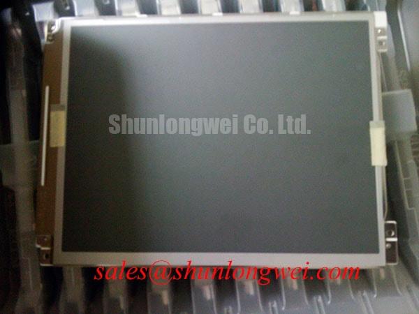
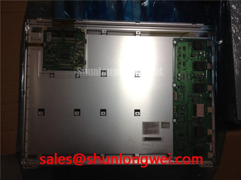
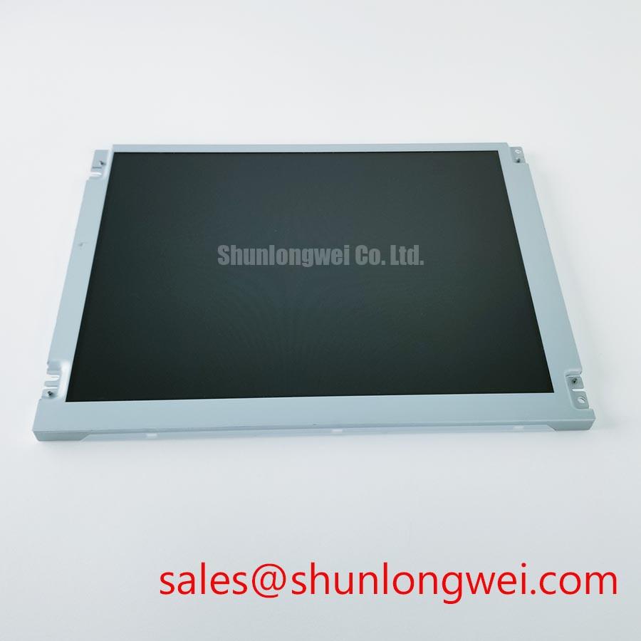
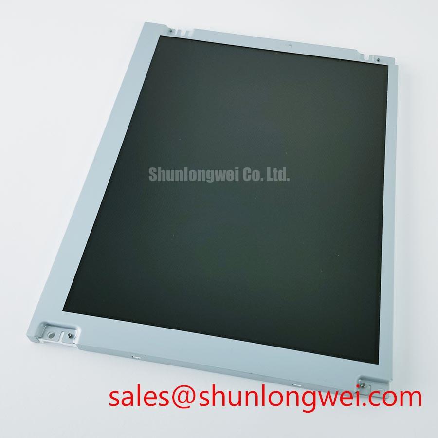
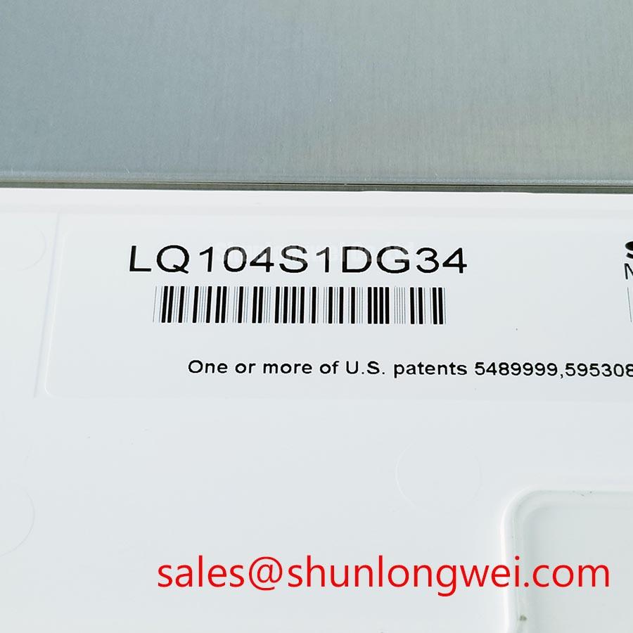
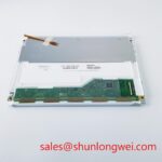
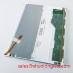
Incoming inspection should begin before the panel is installed in the machine. Photograph the label and connector condition, inspect the bezel and visible screen surface under controlled lighting, and compare the module with the approved purchase description. The confirmed package description is TFT LCD Display Module; detailed dimensions, active area, resolution, pixel defect limits, and backlight construction are not included in the available factory parameter list and should be obtained before accepting a production replacement.
A practical bench screen check uses full-screen red, green, blue, white, black, and neutral gray images. First inspect the primary colors for permanently bright or dark sub-pixels. Next examine white and gray fields for broad luminance variation, edge shading, or localized shadows. Finally display normal operating graphics and move the image through the region where a suspected defect appears. This sequence separates visible pixel behavior from defects that occur only with particular video content.
A flashlight viewed at approximately 45 degrees can help identify whether a dark area is present in the image path or is primarily a surface reflection. Use low pressure and avoid touching the active area. A dark region that changes with viewing angle may require optical and cover inspection, while a fixed line or localized image defect requires comparison with the controller output and a known-good module. Do not assign a single cause without checking the cable, connector, timing configuration, backlight operation, and panel response.
Automated optical inspection can support production screening when the camera, illumination, test pattern, and acceptance limits are controlled. The inspection limit must come from the approved panel specification or the equipment owner’s quality agreement. Do not introduce a pixel-failure threshold, brightness uniformity percentage, or backlight lifetime figure as though it were an LQ104S1DG34 factory rating when no such value has been confirmed.
Backlight troubleshooting should follow the power path. Check whether the display image is present under suitable lighting, then determine whether the backlight enable and driver output are reaching the panel assembly according to the host documentation. A dark screen can result from absent image data, absent backlight drive, a protection response in the driver, or a connector problem. The diagnostic method should be measurement based. LED backlight lifetime and brightness decay, including any 50,000 hour or 50 percent brightness claim, require a manufacturer source for this exact configuration and should not be assumed.
Long-term static HMI screens also deserve an application review. Image retention risk depends on panel technology, drive conditions, temperature, static content, and operating schedule. Designers should consider screen rotation, periodic content movement, sensible brightness control, and service monitoring where the machine permits these functions. These are design considerations rather than guaranteed characteristics of the LQ104S1DG34.
For broader background on panel interfaces, optical behavior, and selection checks, consult The Ultimate Guide to Industrial TFT LCD Technology while keeping the final acceptance decision tied to the original panel documentation.
Mitigating Gray-to-Gray Response Time Escalation During Cold-Start Machine Power-Up
Cold-start evaluation should be performed with the complete display assembly, not with the loose panel alone. Record the startup image, backlight behavior, text clarity, and touch or controller response at the equipment’s specified environmental limits. The supplied factory data does not confirm an operating temperature range, gray-to-gray response time, sealant construction, or thermal-cycle qualification for the LQ104S1DG34. A stated range such as minus 30°C to plus 85°C must therefore be verified before it is used in an AGV or forklift design approval.
Liquid crystal response can change with temperature, and a slow transition during a cold start may be influenced by panel temperature, controller timing, backlight behavior, or the graphics content itself. Compare a moving test pattern with ordinary HMI screens, then monitor the host supply and display data during startup. If the image is delayed, smeared, or incomplete, check whether the condition clears after warm-up and whether the same behavior appears on a known-good module. This avoids treating one symptom as proof of a single internal failure.
Power sequencing should follow the original panel and controller requirements. The system integrator should verify supply order, reset handling, data enable timing, and backlight activation from the applicable documentation. If the host begins transmitting before the display is ready, the result may be a blank image, transient white screen, or residual image during shutdown. Corrective timing should be selected by the system engineer and validated across the permitted temperature range rather than copied from an unrelated display.
FPC and connector reliability deserve a separate mechanical check. Confirm that the flex cable is not trapped against a sharp chassis edge, pulled sideways by the cover, or repeatedly flexed at the connector root. The locking mechanism should close evenly, and the cable should remain fully seated after vibration testing. A visual inspection alone may not reveal intermittent contact, so compare continuity and signal quality before and after the planned mechanical movement test.
For differential links, preserve the intended pair geometry and keep discontinuities under control through the flex transition. A 100 ohm plus or minus 10 percent target and a skew limit of 50 ps may appear in a particular system design, but neither value is confirmed here as an official LQ104S1DG34 parameter. The responsible method is to obtain the host interface requirements, model or measure the complete path, and verify image stability under electrical noise, vibration, and temperature conditions relevant to the finished machine.
Enclosure stress should also be checked after thermal cycling. The panel must not be clamped unevenly, twisted by the bezel, or loaded by a cover that expands differently from the display frame. Sealing, gasket compression, condensation control, and dust protection are assembly-level responsibilities. If the LQ104S1DG34 is evaluated for a rugged AGV or forklift telematics display, approval should follow inspection of the complete enclosure, cable routing, power sequence, optical performance, and environmental test evidence rather than the TFT module designation alone.