Content last revised on October 10, 2026
Dynamic Contrast Ratio Stabilization and Liquid Crystal Birefringence Temperature Tracking
| Manufacturer | NEC |
|---|---|
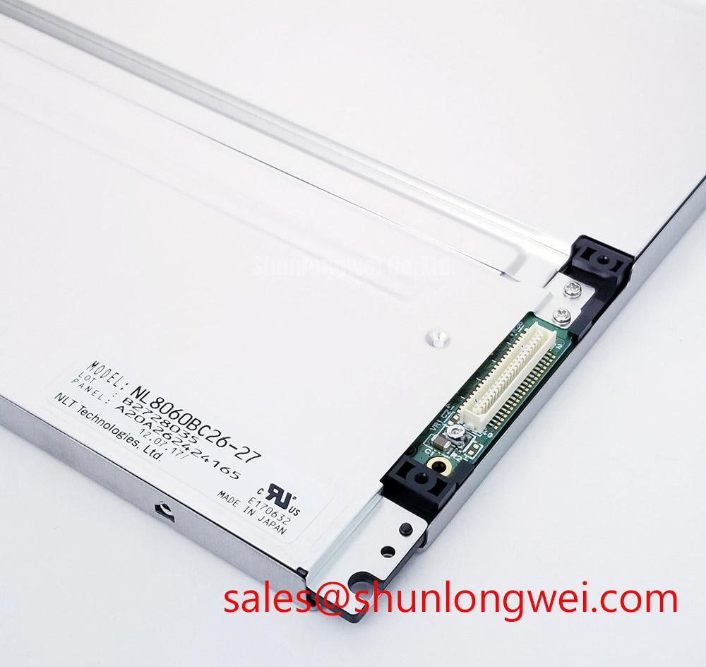
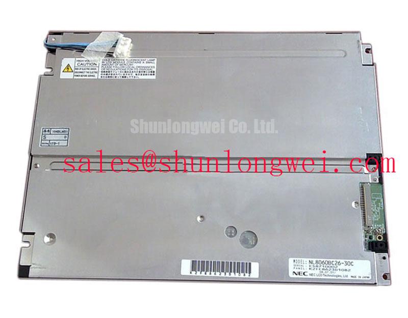
| Model | NL8060BC26-20 |
| Product category | Industrial TFT-LCD module |
| Display construction | TFT-LCD active matrix color display module |
| Specification status | Decoded baseline and standard form factor |
| Application reference | CNC operator panels and robot teach pendants, subject to system compatibility checks |
Start the bench check by displaying a neutral gray pattern, then inspect the screen from the operator’s normal position and from the upper, lower, left, and right sides. The NL8060BC26-20 is identified as a TFT-LCD active matrix color display module; the exact viewing-angle, contrast, response-time, and optical stack values should be taken from the panel documentation used for the equipment under repair.
Gray-scale inversion and color shift are optical behaviors that can become more visible when the liquid-crystal response changes with temperature or when the viewer moves away from the intended axis. Do not classify a panel as an IPS or MVA device from appearance alone. Compare black, mid-gray, and white test fields at a fixed brightness level, then repeat the inspection under the enclosure lighting used in the CNC operator panel or robot teach pendant.
Ambient reflections can also be mistaken for unstable contrast. A Design Consideration is to evaluate the display under the actual machine-room illumination rather than relying only on a dark service bench. Surface anti-glare treatment, if present in the installed assembly, can alter perceived sharpness and black level. A 45-degree inspection with a controlled flashlight helps separate surface reflection from a true image-level defect.
Backlight control belongs to the host system unless the original panel documentation defines the relevant interface. For a replacement evaluation, the system designer may investigate PWM behavior in the approximate 200 Hz to 1 kHz range as a general Design Consideration, checking brightness linearity, visible flicker, acoustic interaction, and camera-band artifacts. This is not an NEC factory specification for this model.
For industrial HMI optical selection, engineers can also review Tianma Industrial TFT Display Solutions and compare the documented optical characteristics of the installed assembly rather than assuming that another TFT module has identical birefringence or viewing performance.
TTL 24-Bit Digital RGB Bus Synchronization and Logic Power Rail Verification
Confirm the host interface before applying power: identify the panel connector, map the red, green, and blue data groups, locate pixel clock and synchronization signals, and compare the existing cable orientation with the replacement documentation. The product category identifies this unit as a TFT-LCD module, but it does not by itself establish a universal TTL voltage, pin assignment, JEIDA mapping, VESA mapping, or supply sequence.
When the source system uses a TTL 24-bit RGB bus, a split image, incorrect colors, missing vertical regions, or unstable synchronization should be investigated through the complete signal path. Check whether the source timing, pixel clock polarity, horizontal timing, and vertical timing correspond with the original panel configuration. A mapping error can produce a clean but incorrectly colored image, while timing disagreement may create rolling, tearing, or intermittent frame loss.
Logic-rail verification should follow the original equipment documentation. Do not assume that a replacement LCD accepts both 3.3 V and 5.0 V. Confirm the required voltage, enable order, reset behavior, and backlight control from the panel and host records before connection. During power-up, capture the rail and enable signals together; the engineering target for a particular design may specify a rise-time window such as 0.5 ms to 10 ms, but that range is a system-level Design Consideration rather than an official rating established here.
For high-speed board-to-panel routing, maintain a consistent return path and control impedance according to the host interface design. A nominal 100-ohm differential environment may be relevant to differential display links, but it should not be imposed on this model unless the installed interface is confirmed as LVDS. TTL RGB is a single-ended parallel bus and must be treated differently from an LVDS link.
Cold service conditions can lengthen liquid-crystal gray-to-gray transitions and make moving text appear less crisp. If the equipment is operated below room temperature, monitor image response during warm-up and verify any enclosure heating function as part of the complete system. The panel should not be assigned a heater-strip capability unless that function is documented for the specific assembly.
Incoming Benchtop Inspection: COG and TAB ACF Integrity
Use a controlled primary-color test sequence before installing the display into a machine. Red, green, and blue full-screen fields reveal different classes of nonuniformity, while a white field exposes dark shadows, dust-like marks, and uneven illumination. Keep the source timing unchanged between tests so that a cable or controller problem is not mistaken for a panel defect.
Inspect the active area at normal viewing distance first, then use a flashlight at approximately 45 degrees to examine dark regions and edge transitions. This method can help distinguish a backlight distribution issue from a line defect associated with the bonded driver area. A shadow that changes with viewing angle may be optical or reflective; a fixed vertical or horizontal line that remains aligned with the image typically requires closer examination of the panel, cable, and controller path.
If COG or TAB bonding areas are present, they should be handled without pressure. Do not press the glass edge, flex tail, or bonded region to force an image change. Pressure-based testing can create a temporary contact condition and may damage the assembly. Compare the suspected area with a known-good signal path, inspect the connector retention, and repeat the color sequence after the panel reaches the service temperature.
Sub-zero operation requires additional care because liquid-crystal viscosity and response behavior change as temperature falls. If the host equipment uses controlled warming, assess the actual temperature transition and image recovery as a complete system function. Do not describe a heater, optical bonding layer, sealing compound, or specific backlight plate construction as part of this NEC model without corresponding documentation.
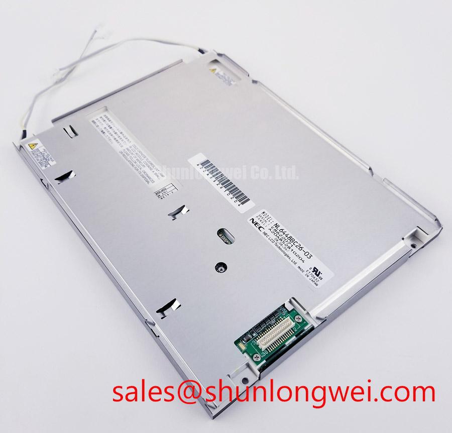
For a same-class replacement study, the NL6448BC20-08E may be reviewed as a separate display option, but mechanical outline, connector position, timing, optical performance, and mounting compatibility must be compared independently rather than inferred from the model family.
Radiated Emissions Compliance and Backplate Grounding Evaluation
Begin electromagnetic troubleshooting with the complete installed assembly, because a display module alone cannot claim compliance with system-level CISPR Class A or Class B limits. Pixel jitter, horizontal noise bands, or intermittent image disturbance near a variable-frequency motor drive may originate from cable routing, return-current paths, connector shielding, controller timing, or the drive enclosure.
A Design Consideration for industrial integration is to keep the display cable path separated from high-current switching conductors and to provide a deliberate chassis reference at the enclosure interface. Where a shielded FFC or LVDS cable is actually used, evaluate shield termination around the connector and backplate so that the return path is continuous rather than relying on a long pigtail. Common-mode ferrite components can be assessed when measurements show a conducted or radiated common-mode problem, but their suitability depends on the cable type and frequency spectrum.
Do not transfer an LVDS grounding method to a confirmed TTL RGB interface without first identifying the electrical topology. A 360-degree shield termination, star-ground arrangement, or ferrite component is an integration option, not an NEC factory feature of the NL8060BC26-20. Validate any modification with conducted and radiated measurements in the final enclosure, including the motor-drive operating states that reproduce the field symptom.
Mechanical bonding, backplate contact, and cable strain relief should be checked after the display has been mounted. Vibration can change connector contact pressure or move a cable into a noisy field even when the image is stable on the bench. The Industrial Display and HMI Solutions resource provides additional system-level context for evaluating display integration in demanding industrial environments.
Field Alert: Disconnect system power and allow stored energy to discharge before inserting or removing the display cable, because live connection can expose signal contacts to unintended voltage or ground transients.
For manufacturer-level reference material, consult NEC Display Solutions and match the replacement against the original system drawings, connector definition, timing configuration, mechanical envelope, and optical requirements.