






Content last revised on September 10, 2026
Mitigating Gray-to-Gray Response Time Escalation during Cold-Start Machine Power-Up
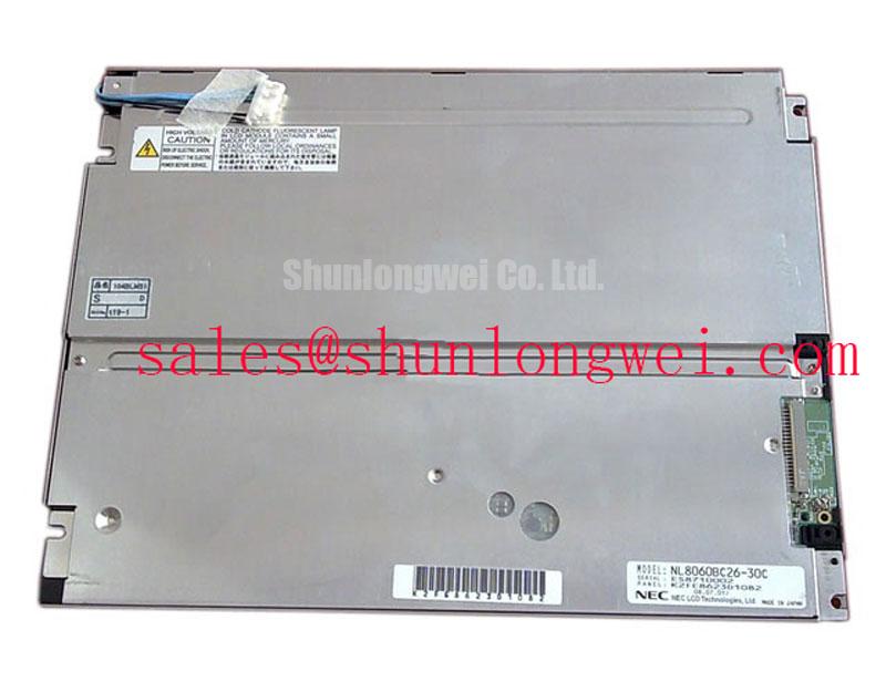
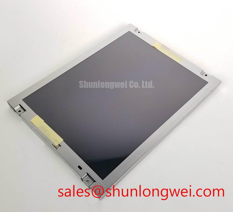
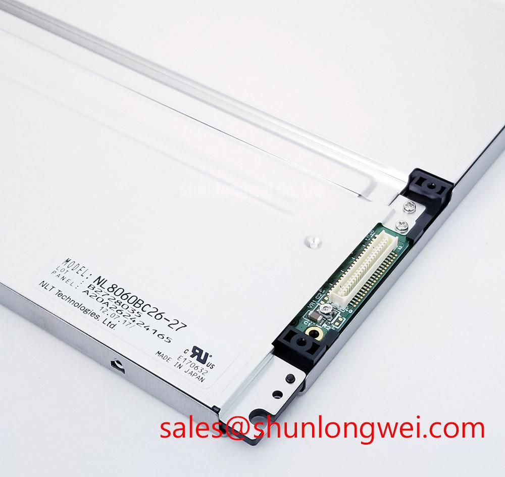
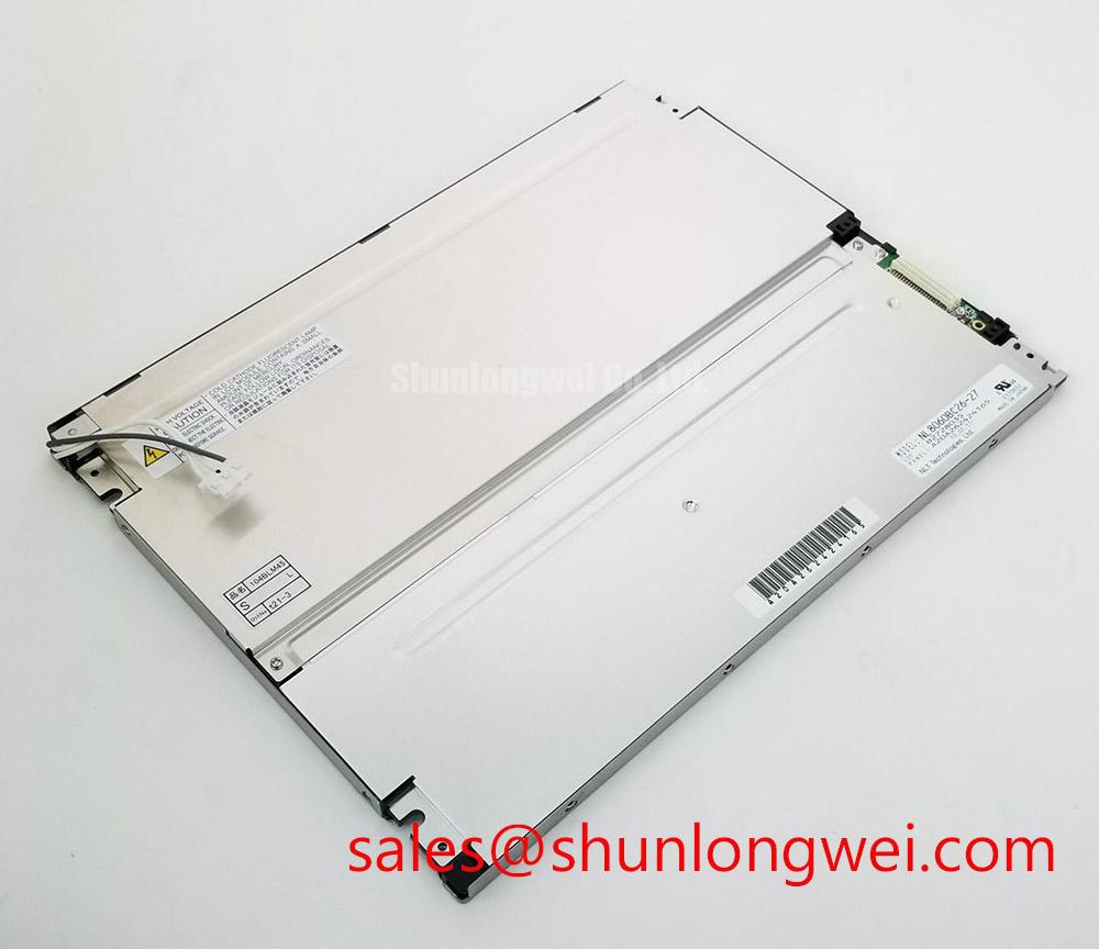
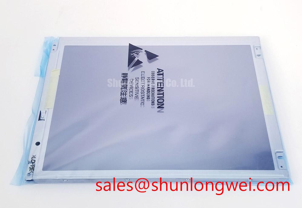
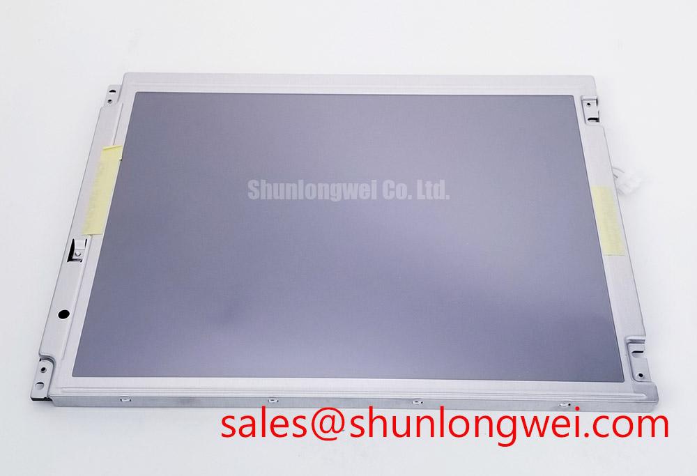
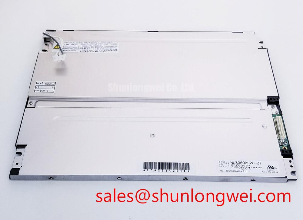
Begin incoming inspection with the power disconnected: check the NEC NL8060BC26-27 TFT LCD Display Module for cracked glass, damaged frame areas, contaminated connectors, and visible marks before applying any system power.
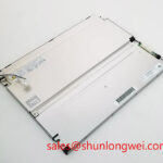
The NL8060BC26-27 is identified in the available factory information as an Industrial Grade LCD/HMI Panel manufactured by NEC. Its package type is a TFT-LCD Display Module. The available factory record does not provide confirmed values for resolution, active-area dimensions, interface type, supply voltage, backlight architecture, luminance, contrast ratio, viewing angle, or operating temperature. Those values should be checked against the original NEC panel documentation and the display installed in the target equipment.
| Model | NL8060BC26-27 |
| Manufacturer | NEC |
| Product category | Industrial Grade LCD/HMI Panel |
| Package or enclosure | TFT-LCD Display Module |
| Specification status | Product identification recorded; detailed specifications require confirmation |
For procurement and repair work, the replacement decision should be based on connector position, mechanical envelope, optical requirements, signal format, backlight connection, and the host system’s power sequencing. A similar model such as NL10276BC16-06 may be reviewed as a separate reference, but model similarity alone does not establish interchangeability.
Mitigating Gray-to-Gray Response Time Escalation during Cold-Start Machine Power-Up
When this panel is evaluated for a high-voltage substation protection or SCADA dispatch console, the first cold-start check should compare the image during initial power-up with the image after the panel reaches a stable operating condition. Slow transitions, temporary color shifts, or residual image effects should be recorded against the system temperature and the display controller’s startup sequence rather than assigned to the panel without measurement.
Liquid-crystal response can vary with temperature as a general display technology consideration. If the equipment operates across a wide thermal range, the system integrator should verify the actual operating-temperature specification for the NL8060BC26-27 from the original NEC documentation. The perimeter seal, bonding arrangement, and enclosure sealing method should also be confirmed from approved mechanical documentation. The available factory information supplied for this product does not verify a specific optical-bonding construction, sealant compound, or thermal-cycle qualification.
The video path requires the same discipline. If the host uses LVDS, the integrator should confirm the exact receiver format, lane arrangement, clocking, connector pinout, termination, and cable requirements from the panel documentation. A differential link target such as 100 Ω ± 10% may be used only where it is required by the selected interface standard and the host design; it is not an official NL8060BC26-27 parameter in the supplied data. Pair skew, common-mode range, and eye opening should be verified at the panel connector with the installed cable and controller.
For cold-start troubleshooting, capture the display enable signal, backlight enable signal, supply rails, and video clock relationship with an oscilloscope where those signals are present. A white screen, delayed image, or intermittent synchronization can involve controller timing, backlight control, connector seating, or supply behavior. The evidence should be compared with a known-good signal path before replacing the module.
Aluminum Heat Spreader Sizing and Thermal Interface Placement along Narrow Display Edges
Thermal evaluation should begin with an infrared survey of the display perimeter, controller area, backlight region, and nearby power electronics after the console has operated under its normal image load. This identifies local heating patterns without assuming that the LCD module itself contains a specified heat spreader or optical plate construction. The supplied factory data does not confirm an aluminum rail, PMMA light guide, LED lifetime rating, L70 value, or B50 value for this model.
An aluminum spreader can be considered when the assembled enclosure produces a localized hot area, but its size, contact pressure, insulation, and thermal interface must be determined by the complete mechanical design. The spreader should not obstruct the panel frame, compress the glass, interfere with the connector, or create a conductive path to exposed circuitry. Designers should validate the proposed arrangement by measuring panel temperature, image stability, backlight uniformity, and enclosure airflow during representative operation.
Thermal interfaces should remain external and controlled. Do not place adhesive, gap filler, or metal hardware over an unapproved active area or flexible connection. The original mounting drawings should define where force can be applied. Any modification to the frame or rear surface should be reviewed for mechanical stress, optical pressure marks, and service access.
Clock jitter and data hold behavior belong to the complete transmitter, cable, receiver, and panel combination. The available official information does not specify TTL or LVDS timing limits for the NL8060BC26-27. When the existing controller is retained, engineers should verify pixel clock behavior, setup and hold margins, and signal quality across the intended temperature window. If the host timing cannot be identified, the original panel documentation should be obtained before selecting a replacement controller.
Static HMI screens also require application-level attention. A fixed alarm page, mimic diagram, or status bar may show persistent image retention depending on panel technology, drive conditions, temperature, and operating pattern. The system designer should verify the panel’s approved usage guidance and consider suitable screen-management behavior where long-term static content is unavoidable. No specific burn-in or retention lifetime is stated in the supplied factory information.
Incoming Benchtop Inspection: COG and TAB Connection Integrity
After the visual check, connect the panel only with the host power removed and the cable orientation confirmed. Inspect the flexible connector for a level insertion, fully closed locking mechanism, and clean contact area. A cable that is slightly skewed can produce intermittent columns, missing rows, unstable color, or a display that changes when the enclosure is moved. These symptoms require controlled comparison and connector inspection rather than a single-cause diagnosis.
The initial image test should use full-screen red, green, blue, white, black, and neutral-gray fields. Record bright pixels, dark pixels, line defects, uneven areas, flicker, and color contamination at a fixed viewing distance. Repeat the test after a normal warm-up period and after a controlled restart. The available specification record does not state a defect-pixel class, acceptance limit, luminance value, or uniformity tolerance, so the purchasing or repair team should use the project’s approved acceptance criteria.
A flashlight held at an oblique angle can help distinguish surface contamination, pressure marks, and some backlight-related shadowing from defects that remain locked to a row or column. This is a diagnostic aid, not a proof of COG or TAB damage. Do not press the glass edge, driver area, or flexible bonding region while testing. Mechanical probing can create a new fault and does not reproduce normal equipment operation.
💡 Bench Tip: Use ESD protection and keep the flexible cable perfectly parallel to the connector before closing its lock; never insert or remove the display cable while power is applied.
Backlight behavior should be assessed separately from pixel drive behavior. Check whether the entire field illuminates evenly, whether brightness changes with the host dimming command, and whether flicker follows the controller’s dimming signal. A PWM range such as 200 Hz to 1 kHz must not be attributed to this model unless it is confirmed by the backlight documentation. The correct dimming frequency, duty-cycle limits, enable polarity, and current-control method remain system and panel specific.
If a line defect remains fixed while the backlight appears uniform, inspect the video source, connector seating, cable continuity, and controller output before concluding that the panel bonding is defective. If only a region of illumination is affected, compare the backlight wiring and driver behavior with the panel’s approved electrical documentation. No internal ACF construction or microscopic fracture condition should be inferred without manufacturer-level evidence.
Eye-Diagram Voltage Margin and Differential Noise-Floor Verification in High-Vibration Bays
For installation near variable-frequency motor drives or other high-noise equipment, begin by separating mechanical and electrical observations. Monitor the display while the equipment is stationary, during vibration, and during motor acceleration. Log the exact time of horizontal bands, pixel jitter, color changes, or loss of synchronization and compare those events with the host controller, cable movement, grounding changes, and drive switching activity.
A shielded FFC or LVDS cable can be evaluated as part of the complete signal route, but the appropriate shield termination and grounding method depend on the controller, enclosure, cable construction, and system safety design. A 360-degree shield connection and ferrite suppression may be considered where they reduce measured common-mode noise, but neither arrangement is an official factory feature confirmed for the NL8060BC26-27. Engineers should verify the result with the installed cable and an oscilloscope rather than relying on a generic wiring prescription.
Eye-diagram testing should be performed at the panel-side interface when the interface type and electrical limits are confirmed. Compare differential amplitude, common-mode behavior, edge quality, eye opening, and timing margin with the limits specified for the actual transmitter and receiver. If the system uses a different signaling format, an LVDS test method should not be applied by assumption. The model’s supplied factory record does not state an interface voltage, data rate, eye-mask limit, or receiver tolerance.
Grounding changes should be introduced one at a time. Check protective earth continuity, cable shield bonding, controller reference potential, and the physical routing distance from high-current switching conductors. Minimize unnecessary loop area and keep sensitive display wiring separated from power switching paths, then verify peak noise and synchronization margins during the actual switching test. EMC compliance belongs to the complete assembled equipment; the LCD module itself should not be represented as independently certified to an enclosure-level EMC standard.
Outdoor or brightly illuminated control rooms require an optical acceptance test under the actual enclosure window and ambient lighting. The supplied information does not confirm a contrast ratio above 500:1 at 50,000 lux, an anti-glare coating, a wide-view IPS or MVA structure, or a specific viewing-angle compensation method. Those characteristics must be verified in the official panel datasheet or by controlled inspection of the installed unit. Check the screen from the intended operator positions, including off-axis color change, reflected glare, black-level visibility, and text legibility.
For system-level display architecture, the related NL10276BC30-24D can be reviewed as a separate display-solution reference. It should not be treated as a confirmed accessory or electrical companion for this model without documentation. The broader The Ultimate Guide to Industrial TFT-LCD Technology provides additional background for checking panel interfaces, optical behavior, and integration constraints.
Before approving the NL8060BC26-27 for a repair, verify the original panel identification, connector arrangement, mechanical fit, power requirements, display timing, backlight control, and environmental ratings. Where any value is absent from the available factory record, the original NEC documentation and the equipment service manual should control the final installation decision.