
Content last revised on September 22, 2026
High-Nits Edge-Lit LED Rail Thermal Dissipation and Light Guide Preservation
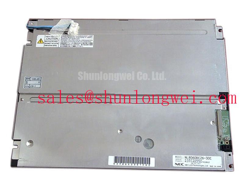
For an AGV or forklift telematics display, start by determining whether the replacement panel uses the same backlight arrangement as the removed unit. The model identification supplied here confirms the TFT-LCD display category, but it does not establish a specific LED rail design, light guide material, brightness rating, or optical lifetime figure. The system integrator should therefore verify the original panel documentation rather than assuming that a high-brightness edge-lit arrangement is present.
When the assembly does use edge-mounted illumination, the practical thermal objective is to prevent concentrated heat from accumulating along one narrow display edge. A chassis interface or aluminum heat-spreading rail can be evaluated as a Design Consideration when it provides a controlled path from the backlight region to the enclosure. The rail should not press against the glass, flex the frame, or obstruct the intended airflow path. Its size, contact area, surface treatment, and attachment method remain system-level decisions that require validation during the actual brightness and enclosure tests.
Do not infer PMMA light-guide composition, yellowing resistance, L70 performance, or B50 life for this model unless those values appear in the applicable NEC documentation. A visible warm band near one edge can result from several conditions, including driver regulation, uneven mechanical contact, blocked ventilation, or a failing optical element. Record the symptom at minimum and maximum permitted brightness, then compare the distribution with a known-good display under the same enclosure conditions.
PWM behavior also requires confirmation at the complete assembly level. If the installed backlight driver uses PWM, the controller frequency, duty-cycle response, enable polarity, and dimming interface should be checked against the driver documentation. A proposed operating range such as 200 Hz to 1 kHz is a general bench evaluation reference, not an official parameter of the NL8060BC26-30C. Use an oscilloscope to check the enable and dimming waveforms while observing visible flicker, acoustic noise, and brightness linearity. The final setting should be selected by the system engineer after testing the display, driver, enclosure, and camera-based inspection requirements together.
For a rugged vehicle display, vibration and thermal expansion can alter contact pressure around the frame and cable. The mounting design should distribute mechanical load through the approved bezel or carrier rather than through the active glass. Seal selection, compression, and service access should also be reviewed if the panel is installed in a dusty warehouse vehicle or exposed telematics enclosure. These are integration considerations and should not be presented as factory environmental ratings for this particular model.
Suppressing Acoustic Capacitor Buzz and EMI Across the Dimming Control Path
During a black-screen service call, separate the display optical fault from the backlight power fault before replacing the panel. Check whether image data is present while illumination is absent, and inspect the backlight enable and supply behavior using the system schematic. The NL8060BC26-30C data supplied here does not confirm CCFL ignition voltage, LED current, PWM ratio, acoustic limits, or a backlight half-life value. Do not apply a CCFL ignition assumption or a constant-current LED assumption without first identifying the installed driver.
Acoustic buzz from a display assembly can be coupled to switching components, magnetic parts, ceramic capacitors, mechanical brackets, or enclosure panels. Changing the dimming frequency may alter the audible result, but it is not a guaranteed cure. Treat frequency adjustment as a Design Consideration: observe the driver waveform, listen with the enclosure assembled, and check brightness stability and conducted noise at the same time. If the sound changes with load or duty cycle, correlate it with the electrical waveform rather than assigning the cause to the LCD module alone.
For the signal interface, first identify whether the original assembly uses TTL, LVDS, or another interface by consulting the panel drawing and cable marking. The supplied factory summary does not specify the interface standard, pinout, clock frequency, data mapping, jitter tolerance, or setup and hold limits. A replacement cable should therefore not be wired from a generic LVDS or TTL pinout. Confirm power, ground, control, clock, and data assignments from the original documentation and verify that the host transmitter uses the same mapping.
Where a differential interface is confirmed, route the pair as a controlled transmission path with a continuous reference plane and minimal discontinuities. A nominal 100 ohm differential target is a common system design reference for LVDS routing, not a verified specification for this model. The board designer must establish the impedance, pair skew, connector discontinuity, and clock margin from the transmitter and receiver documentation. Oscilloscope checks at the panel end are more useful than judging cable quality by appearance alone.
EMI evaluation should be performed with the display installed in its final metalwork, with the motor controller, radio, and backlight driver operating in their normal states. Check for image corruption, intermittent lines, loss of synchronization, and brightness modulation while nearby switching loads change. The display module itself must not be described as independently passing a complete system EMC certification. Compliance depends on the host electronics, cable routing, enclosure, grounding, filtering, and operating configuration.
⚠️ Field Alert: Disconnect system power and allow the supply rails to discharge before removing or inserting the display cable, because contact during live service can stress signal and power pins.
TTL 24-Bit RGB Bus Synchronization and Logic Power Verification
When the screen shows split images, unstable colors, missing columns, or intermittent synchronization, begin with the signal path and power sequence rather than immediately condemning the glass. Confirm that the host controller, timing controller, cable, and panel are specified for the same interface family. The phrase “TTL 24-bit RGB” must not be applied to the NL8060BC26-30C as a confirmed factory feature unless it is stated in the applicable panel drawing.
Logic supply verification should follow the original documentation. Do not select between 3.3 V and 5.0 V by visual similarity or by comparing another NEC display. Measure the rail at the panel connector during power-up and operation, observing rise behavior, ripple, and transient response. The values 0.5 ms to 10 ms sometimes appear in generic power-sequencing discussions, but they are not verified specifications for this model. The system integrator should confirm the permitted voltage and timing from the original panel documentation.
Power sequencing matters because a display can react differently when logic power, backlight enable, reset, and video data become active in an unintended order. Record each control signal relative to the panel ground and compare the result with the known-good unit. If no original timing information is available, the engineering team should test conservative sequencing experimentally while monitoring for start-up artifacts and repeated reset behavior. Avoid presenting a bench starting point as an NEC requirement.
For a confirmed differential display link, impedance control and pair symmetry are sensible routing practices. A 100 ohm differential target with a 10 percent tolerance is a common engineering reference, not an official NL8060BC26-30C rating in the supplied information. The PCB stack-up, connector, flex cable, and receiver specification determine the acceptable result. Clock skew should be evaluated against the transmitter and receiver timing budget; a generic 50 ps limit must not be assigned to this model without documentary support.
JEIDA and VESA color mapping are also system-specific. Incorrect mapping can produce swapped colors, abnormal grayscale, or an image that appears divided even though the panel is receiving a valid clock. Compare the red, green, and blue bit order with the host configuration and the original cable documentation. Check clock polarity, data-enable behavior, horizontal timing, and vertical timing using a known-good signal capture. If the panel image changes when the cable is gently repositioned, inspect connector retention and contact condition before changing software parameters.
For potential replacement evaluation, the related NL10276BC16-06 may be reviewed as a separate display option, but electrical, mechanical, optical, and interface compatibility must be demonstrated independently. The NL10276BC30-24D may also be examined as a related display solution in a wider power and display architecture; it should not be treated as an automatic substitute or a confirmed backlight driver for this model.
Incoming Benchtop Inspection for COG and TAB Connection Integrity
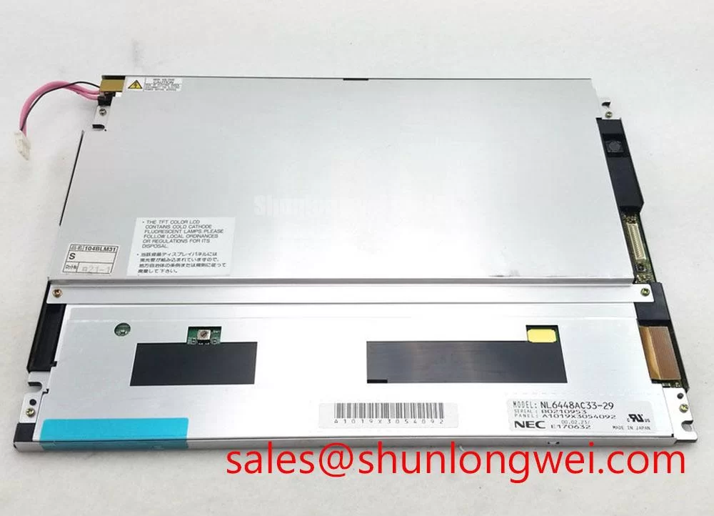
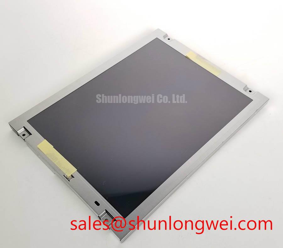
Incoming inspection should begin with a clean, dry work surface and a visual comparison against the removed display. Check the bezel, glass edge, flex tails, connector latch, protective films, and mounting points under neutral lighting. COG and TAB bonding details are not included in the verified product summary, so inspection should identify observable defects without claiming a particular internal bonding structure or failure rate.
A practical three-stage color check can be used as a Design Consideration after the correct host interface and power conditions have been confirmed. Display a full red field, then a full green field, and then a full blue field. Add a full white and full black field when the controller permits. Look for persistent vertical lines, horizontal bands, isolated bright points, nonuniform patches, color contamination, and areas that respond differently during a slow image transition. Capture photographs with fixed exposure so that service records remain comparable.
A dark-shadow inspection can help separate illumination behavior from image-generation behavior. In a dim inspection area, place a flashlight at approximately 45 degrees to the front surface and examine the black field without pressing the glass. A shadow that changes with the illumination angle may be related to surface reflection, optical uniformity, or backlight distribution. A fixed line that remains aligned with image data may require inspection of the signal path, timing controller, or panel bonding region. This method narrows the investigation; it does not prove a single root cause.
Do not press the active area, flex the glass, or probe exposed bonding regions during incoming inspection. If a line appears after mechanical handling, compare it with the pre-test photograph and review connector seating, cable strain, and carrier alignment. For an AGV or forklift display, the final evaluation should include the installed bezel and cable routing because vibration, enclosure pressure, and repeated thermal cycling can change the symptom.
Longer-duration testing should use the actual controller, backlight driver, enclosure, and operating image set. Monitor display stability, brightness behavior, connector temperature, and intermittent artifacts while the system transitions between normal screens, warning screens, and black backgrounds. The technical background for TFT display operating principles, selection factors, and common misconceptions is available in The Ultimate Guide to Industrial TFT-LCD Technology. Any environmental rating, optical lifetime, sealing performance, or service-life claim for the NEC NL8060BC26-30C still requires confirmation from the applicable factory documentation and validation in the completed equipment.