

Content last revised on October 18, 2026
Mechanical Stress and Glass-Substrate Fracture Prevention
- Check the incoming label against LQ050Q3DG01 and confirm the display family before unpacking.
- Inspect the glass edge, frame, connector area, and flexible cable for transport stress under controlled lighting.
- Compare the replacement panel’s mechanical envelope and mounting points with the existing machine-tool HMI assembly.
- Prepare an ESD-controlled bench before connecting the display to the controller or backlight circuitry.
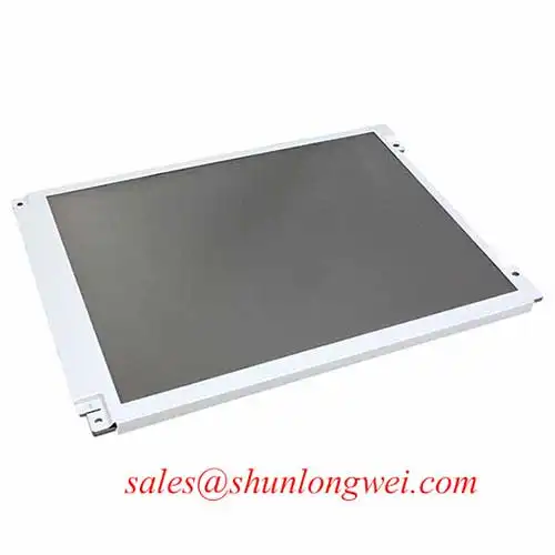
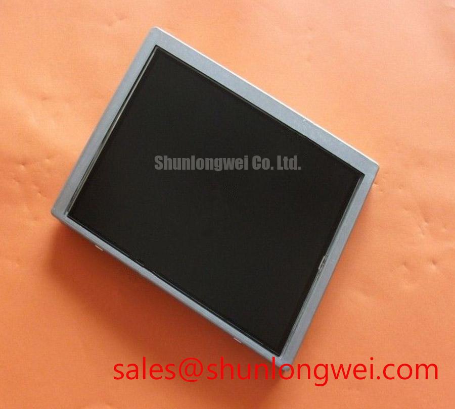
The LQ050Q3DG01 is identified as a Sharp TFT-LCD active matrix color display module for industrial LCD and HMI panel integration. Its supplied product classification is Industrial Grade LCD/HMI Panel, with a decoded baseline and standard form factor status. The available product identity does not establish a complete electrical timing table, optical performance table, or connector pin assignment, so those interface details belong in the replacement verification record rather than being assumed during installation.
Start the optical inspection with the panel unpowered and use low-angle illumination to reveal frame distortion, glass-edge impact marks, and uneven seating. A small mechanical twist can create an intermittent line defect that changes as the chassis is tightened, while a backlight irregularity normally remains distributed across a larger illuminated area. This distinction is useful when screening a Sharp LCD module before it enters a factory automation machine-tool HMI operator terminal.
Apply a standardized primary-color sequence using full-screen red, green, blue, white, and black images. Record the panel response at the same viewing angle and brightness setting, then repeat the sequence after the display has reached a stable operating condition. A narrow vertical or horizontal line that remains fixed across multiple colors warrants inspection of the glass edge, cable alignment, and frame pressure. A dark area that changes with the backlight setting should be separated from a pixel-addressing defect before mechanical intervention.
The 45-degree flashlight method is a practical bench technique for locating shadow boundaries and localized illumination changes. It should be used as a comparative inspection method, not as a substitute for the panel’s optical specification. Direct sunlight can overwhelm visual judgment, so any contrast assessment should use controlled ambient conditions. If the host design requires a stated contrast target, anti-glare behavior, or stable readability above 500:1 at 50,000 lux, the complete panel documentation and the assembled front window must be evaluated together; these values are not established here as LQ050Q3DG01 factory specifications.
🔧 Bench Diagnostic: Keep the flexible cable flat and aligned with the connector before locking it, because sideways insertion force can create intermittent image faults that resemble a driver defect.
For optical and mechanical background relevant to industrial operator panels, review the Industrial Display & HMI Solutions engineering guide. A same-size or same-resolution comparison should be treated as a separate compatibility exercise; the LQ057Q3DC03 may be useful as a reference point, but its dimensions, interface, and mounting details must not be transferred to this model.
TTL RGB Bus Synchronization & Logic Power Rail Verification
Verify the host controller’s RGB data mapping before judging a split-screen image as a defective panel. TTL RGB systems can use different bit ordering and synchronization conventions, including JEIDA or VESA-style mapping, and a mismatch may produce incorrect colors, displaced image regions, or unstable pixel data. The required mapping for the LQ050Q3DG01 must come from the panel documentation and the original machine wiring record.
Power sequencing should be observed with an oscilloscope at the panel connector rather than inferred from the controller’s nominal supply label. The integration checklist supplied for this evaluation references a logic rail of either 3.3 V or 5.0 V and a rise-time window of 0.5 ms to 10 ms; these are system integration checkpoints, not confirmed LQ050Q3DG01 factory ratings. The system integrator should verify the correct rail, enable order, reset behavior, and backlight control method from the original panel documentation.
When a 24-bit bus is used, route the data and synchronization signals with consistent reference geometry and avoid unnecessary stubs near motor-control wiring. The suggested 100-ohm differential routing value applies to differential links used elsewhere in the display system and should not be presented as a TTL RGB electrical specification. In a cold-start evaluation, compare frame timing and gray-level response at the required enclosure temperature. Liquid-crystal response can change with temperature, so any heater or software compensation should be selected by the system designer after observing startup behavior.
Sharp’s industrial display resources at Sharp Devices Europe Industrial Display Solutions provide useful manufacturer-level context for display integration. They do not replace the model-specific interface record required for a panel change.
Radiated Emissions Compliance (CISPR Class A/B) via Backplate Multi-Point Star Grounding
Control radiated noise by treating the display, cable, controller, and cabinet as one signal-return system. Pixel jitter and horizontal bands near a variable-frequency motor drive can arise from common-mode coupling, return-current paths, cable placement, or timing margin. The LCD module itself should not be described as independently certified to CISPR Class A or Class B; compliance belongs to the finished equipment and its installation.
A practical design consideration is to keep the display cable away from high-current motor conductors and terminate the cable shield according to the cabinet’s grounding strategy. A continuous shield connection around the cable entry can reduce coupling, while a poorly bonded shield may turn the cable into an unintended antenna. Any common-mode ferrite component should be selected from measured interference behavior and the cable manufacturer’s electrical limits, rather than added as a guaranteed cure.
For differential links in the host display architecture, a nominal 100-ohm impedance with ±10 percent tolerance and a skew budget of 50 ps or less can be used as design considerations when supported by the applicable interface standard. These values are not identified as official LQ050Q3DG01 specifications. Validate the assembled routing with the correct probe arrangement and compare the display signal at the controller and panel ends. The final EMC assessment should be performed on the complete HMI enclosure, including the front bezel, cable shield, backplate, power converter, and motor-drive environment.
Diffuser Film & Prism Sheet Thermal Buckling Prevention under Continuous Full-Duty Operation
Inspect the illuminated screen for local brightness gradients, color temperature changes, or expanding shadow patterns after continuous operation. These observations can indicate a thermal or mechanical interaction within the assembled display system, but they do not identify a particular internal film material or prove a specific failure mechanism. Avoid pressing the optical stack or attempting to flatten a visible area during incoming inspection.
When the HMI runs at high brightness for extended periods, the enclosure designer should evaluate heat flow around the narrow display edges, the rear support, and nearby power electronics. An aluminum heat-spreader rail may be considered where measured hot spots justify additional conduction, provided that it does not load the glass, obstruct ventilation, or create a new stress point. The rail dimensions, interface material, and mounting method are system-dependent and should be established through temperature mapping on the completed assembly.
LED backlight current regulation, PWM dimming, and optical aging must be evaluated from the actual backlight interface. A proposed PWM range of 200 Hz to 1 kHz, a 50,000-hour MTBF statement, or an L70/B50 lifetime value must not be assigned to this model without a supporting Sharp specification or qualified system test. Designers should confirm whether the original controller uses constant-current drive, PWM control, analog dimming, or another method before selecting a replacement driver.
For cold environments, record startup luminance, image response, and backlight behavior from power application through thermal stabilization. If the machine requires operation around −20°C to −30°C, the enclosure thermal design, display operating range, and any temperature compensation must be validated as a complete system. The LQ050Q3DG01 product identity supplied here confirms the Sharp industrial LCD/HMI panel category, but it does not establish those environmental limits or lifetime figures as factory specifications.