Content last revised on September 12, 2026
Sharp LQ050Q5DRQ1 Incoming Inspection and Integration
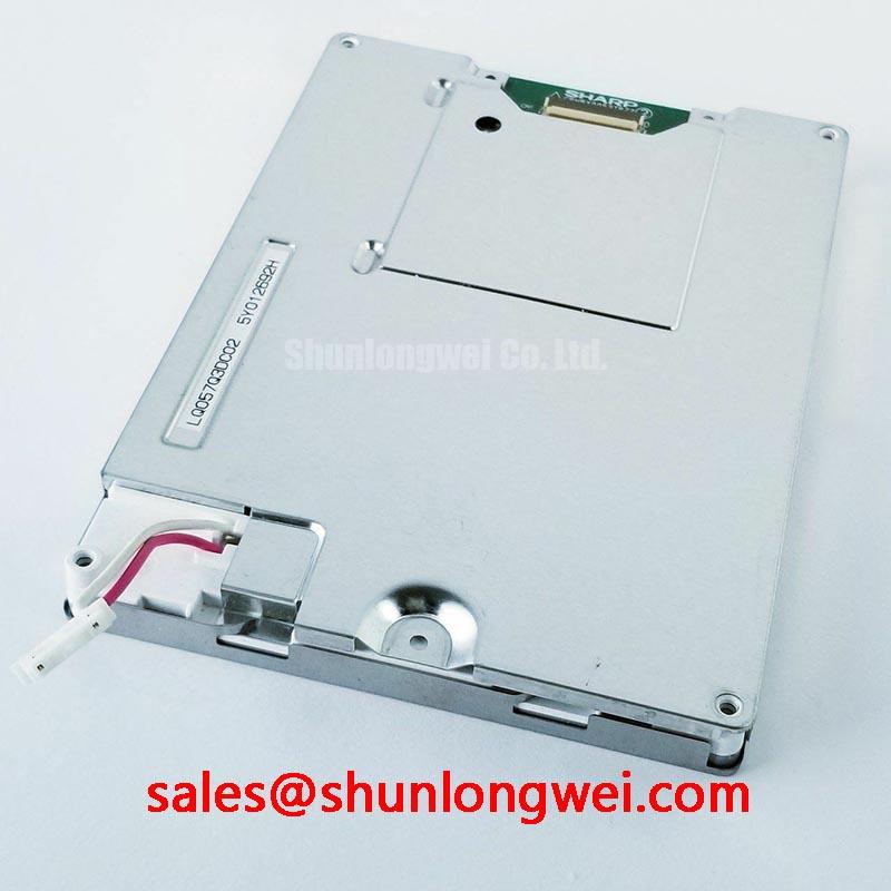
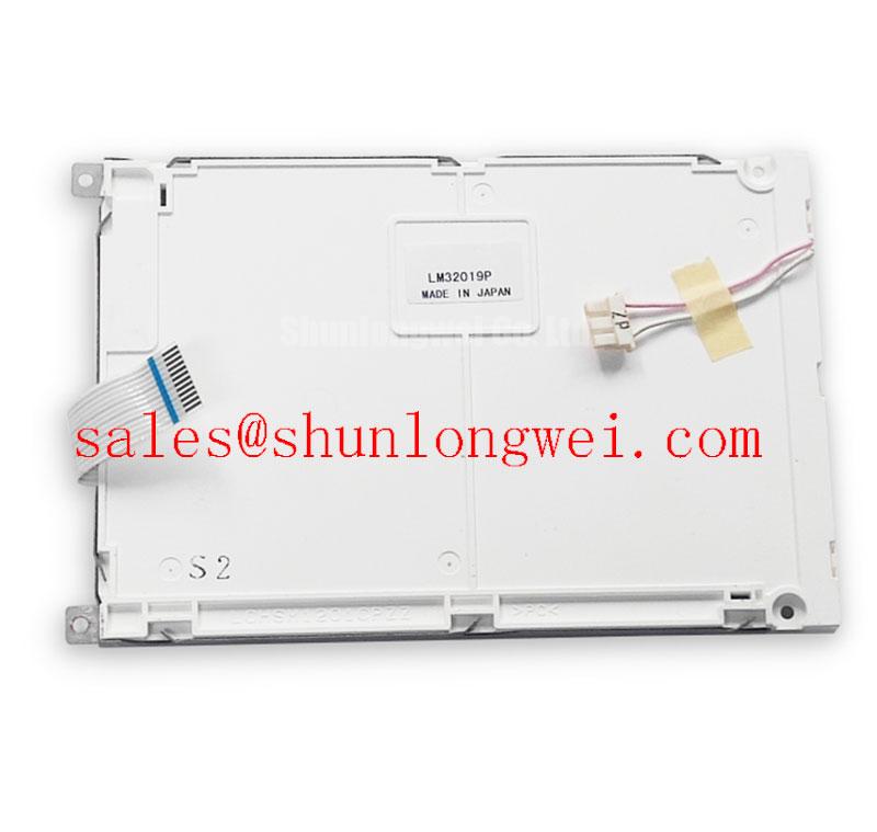
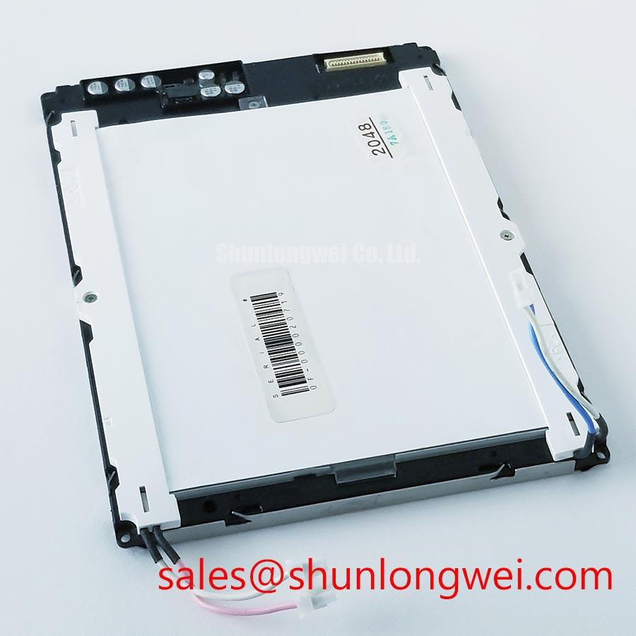
Begin incoming inspection by checking the Sharp LQ050Q5DRQ1 label against the purchase record, examining the TFT LCD module for frame, glass, connector, and surface damage, and confirming that the replacement matches the original panel documentation before applying power.
| Manufacturer | Sharp |
| Model | LQ050Q5DRQ1 |
| Product category | TFT LCD Display Module |
| Package or housing | TFT LCD Display Module |
| Specification status | Verify against applicable Sharp documentation |
The LQ050Q5DRQ1 is a Sharp TFT LCD display module evaluated for industrial HMI replacement and integration work. The supplied factory information identifies the product category and module construction, but it does not establish every electrical, optical, mechanical, or interface value required for a direct system installation. Engineers should verify the original panel documentation for resolution, active area, viewing direction, interface pinout, logic supply, backlight configuration, connector orientation, timing, and mounting details before approving a substitution.
For CNC operator panels and robot teach pendants, incoming inspection should include a full screen test rather than a quick power on check. Display a white, black, red, green, blue, and mid gray field at controlled brightness, then inspect the complete visible area for stuck pixels, dark pixels, line defects, nonuniform illumination, edge leakage, and intermittent artifacts. Repeat the test after the module has reached a stable operating condition, because connector seating, thermal expansion, and backlight behavior can change the appearance of a marginal assembly.
Thermal Cycling Degradation of Polarizer Adhesives & Sealant Gasket Integrity
The Sharp LQ050Q5DRQ1 should be assessed against the actual enclosure temperature profile rather than an assumed industrial temperature rating. The available factory information confirms the TFT LCD display module category, but it does not provide a verified operating range, storage range, thermal shock specification, polarizer adhesive qualification, or perimeter sealant life rating. Any evaluation involving sub zero startup, elevated cabinet temperature, or repeated thermal cycling therefore remains a Design Consideration until supported by the applicable Sharp documentation.
During a thermal evaluation, record the first image appearance, gray transition behavior, contrast consistency, and backlight uniformity at each test condition. Liquid crystal response can become visibly slower at low temperature, while adhesive interfaces and sealing materials may experience mechanical stress during repeated expansion and contraction. These mechanisms should not be used to assign a guaranteed response time or service life to this model without source data. A practical QA record should identify the test temperature, dwell profile, image pattern, warm up time, and any change in image retention or edge appearance.
For a CNC operator panel or robot teach pendant, inspect the perimeter after cycling for lifting, bubbles, moisture traces, discoloration, or a change in the visible active area. If the panel is installed behind a protective window, verify that the window, gasket, and chassis do not apply concentrated pressure to the display. The enclosure designer should manage compression, drainage, ventilation, and contamination control as a system responsibility. The LQ050Q5DRQ1 factory information supplied here does not confirm optical bonding, water resistance, dust sealing, or a particular gasket construction.
When an LED backlight driver is used, its current regulation and dimming behavior should be tested with the selected display assembly. PWM dimming frequency and duty cycle should be chosen by the system designer after checking the driver specification, camera interaction, audible behavior, and visual flicker. The requested range of 200 Hz to 1 kHz is not an official LQ050Q5DRQ1 parameter in the supplied data and should not be treated as a model guarantee.
Radiated Emissions Evaluation and Grounding Considerations
Check the display signal path with the same cable routing and grounding arrangement used in the target machine. A TFT LCD module does not independently carry a complete CISPR Class A or Class B system certification. EMC performance depends on the host controller, cable construction, shielding termination, power conversion, enclosure, grounding architecture, and nearby switching equipment. When the panel is installed near a variable frequency motor drive, pixel jitter or horizontal noise bands may require investigation across the entire signal path rather than attribution to the display alone.
For an LVDS or FFC based design, first confirm the interface type and pin assignment from the original Sharp panel documentation. Do not assume that a connector with a similar physical appearance has the same electrical mapping. Route differential pairs as a controlled, continuous path, avoid unnecessary stubs, and maintain the cable shield or reference connection according to the host equipment design. A multi point star grounding arrangement can be evaluated as a Design Consideration, but its effectiveness depends on chassis impedance, return current paths, cable shield termination, and the frequency content of the disturbance.
Common mode ferrite components may be evaluated when conducted or radiated interference is observed, provided that their impedance, current capability, insertion loss, and effect on signal quality are validated on the complete assembly. Adding a ferrite without checking the differential eye or timing margin can create a new signal integrity problem. Compare the suspect panel with a known good signal path using an oscilloscope or suitable compliance test equipment, and document whether the disturbance follows the display, cable, controller, or power subsystem.
Backlight reliability should be discussed carefully. The supplied official information does not state an LED backlight MTBF, an L70 or B50 value, or a brightness decay curve for the LQ050Q5DRQ1. Values such as 50,000 hours to 50 percent brightness must not be assigned to this model without a Sharp source or a qualified test report. Incoming QA can instead record initial luminance, uniformity, color appearance, driver current, and operating temperature as baseline data for later comparison.
💡 Bench Tip: Disconnect system power before removing the display cable, protect the exposed connector from ESD, and lock the cable straight and fully seated rather than inserting it at an angle.
Backlight Thermal Dissipation and Light Guide Evaluation
The supplied data does not confirm the LQ050Q5DRQ1 luminance level, LED rail geometry, light guide material, optical stack, or backlight service rating. Avoid describing the module as high nits, edge lit, or fitted with a specific light guide material unless the original panel documentation confirms those details. For integration work, inspect the visible backlight distribution and measure the complete assembly after installation in the intended bezel, because chassis pressure, nearby heat sources, and the driver enclosure can alter local temperature and uniformity.
An aluminum heat spreader rail may be considered where the measured edge temperature is higher than the rest of the display assembly. This is an engineering recommendation, not an official Sharp construction requirement. The rail should be electrically, mechanically, and thermally reviewed so that it does not distort the frame, load the glass, obstruct the backlight, or create an unintended conductive path. The system engineer should verify thermal margins during representative display patterns and maximum backlight operation.
Localized optical changes can be screened with full field images and a fixed camera position. Use white and gray patterns to reveal edge shading, bright zones, and gradual nonuniformity, then compare results before and after the module is mounted. Do not infer a material failure from one visual symptom alone. Temperature mapping, connector inspection, driver measurements, and a comparison with a known good unit provide a more reliable fault isolation path.
If the host uses a differential display interface, designers should verify the required characteristic impedance, pair spacing, return reference, and skew budget from the controller and panel specifications. The often cited value of 100 ohms with a tolerance of 10 percent is a system routing target that may apply to a particular interface design; it is not an official LQ050Q5DRQ1 parameter in the supplied factory data. The same applies to a 50 ps skew limit. Validate the actual interface requirement with the panel timing documentation and signal measurements.
For a wider display solution or a different installation envelope, engineers may review the neutral reference page for LM64P10. This is a separate model for comparison, not a blanket replacement recommendation. Mechanical outline, connector definition, optical performance, electrical timing, and firmware compatibility must be checked independently before any cross model decision.
Display Data Mapping and Channel Signal Integrity
Before applying power to a replacement LQ050Q5DRQ1, identify the original panel interface and confirm the host controller mapping. VESA and JEIDA data arrangements are not interchangeable assumptions, and a physically compatible cable can still produce incorrect colors, split screen artifacts, reversed channel behavior, or an unstable image when the data order does not match. The available factory information does not provide the model’s confirmed data mapping, logic supply voltage, power sequence, connector pinout, or timing table.
The system integrator should verify the required supply voltage from the original panel documentation. Do not describe the module as accepting 3.3 V or 5.0 V without a source that specifically applies to this model. Apply power only after checking polarity, enable signals, backlight requirements, and the host controller limits. A controlled rise time can reduce white screen behavior and startup disturbances, but the requested 0.5 ms to 10 ms interval is not an official value supplied for the LQ050Q5DRQ1. The final power sequencing must be validated with the display, controller, and driver connected together.
For even and odd channel verification, display color bars, grayscale ramps, checkerboard patterns, fine vertical lines, and moving text. These patterns make channel swaps, bit order errors, lane discontinuities, and timing instability easier to distinguish than a static logo. If the image separates into regions or shows periodic bands, check mapping, cable orientation, reference ground, connector retention, controller configuration, and power stability before identifying the LCD module as the sole cause.
Viewing angle, contrast ratio, anti glare treatment, sunlight readability, and color shift also require model specific confirmation. The supplied information does not verify IPS or MVA construction, a contrast ratio above 500 to 1, performance at 50,000 lux, or a particular anti glare coating. For a robot teach pendant or CNC operator panel, evaluate the finished HMI from the operator’s actual viewing positions under representative ambient light. Record the selected brightness, screen content, protective window condition, and any reflections that affect readability.
Long term static HMI screens should be checked for image retention during system validation, but no burn in or residual image lifetime claim should be attached to this model without documented test evidence. Use screen rotation, controlled idle content, and brightness management only where these functions are compatible with the machine interface and safety requirements. The display supplier can provide the module, while the equipment designer remains responsible for enclosure sealing, optical stack selection, EMC validation, power sequencing, and final operational qualification.
For related display and backlight topology evaluation, engineers can refer to LMS700KF01-001 as a separate product reference. Broader integration checks for industrial HMI assemblies are also available through Industrial Display & HMI Solutions. Neither reference changes the requirement to verify the LQ050Q5DRQ1 documentation, interface signals, mechanical fit, and complete system test results.