Content last revised on October 8, 2026
Eye-Diagram Voltage Margin & Differential Noise Floor Verification in High-Vibration Bays
With the CNC operator panel or robot teach pendant isolated from power, check the LQ050Q5DR01R identification label, connector seating, cable restraint, and mounting contact points before reconnecting the display assembly. Record the existing controller board and harness configuration so that subsequent measurements refer to the actual equipment rather than a visually similar replacement. Inspect the connector latch and nearby cable insulation for mechanical wear, particularly where repeated pendant movement transfers force into the display housing.
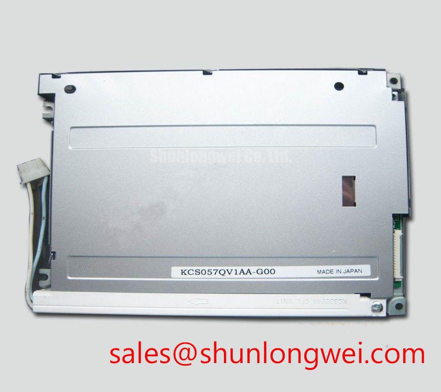
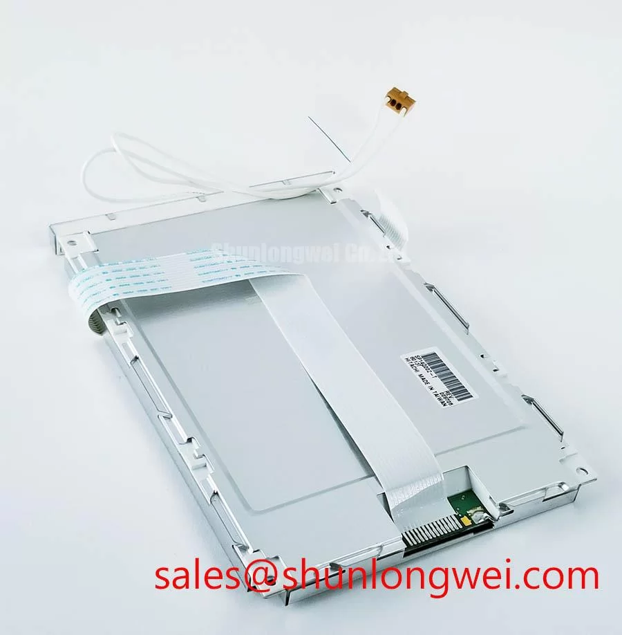
The supplied product identity establishes Sharp as the manufacturer and identifies this product as a TFT-LCD display module in the industrial LCD/HMI panel category. Those details establish the component type; they do not establish its electrical interface, resolution, supply voltage, or environmental limits. The LQ050Q5DR01R product page provides the model reference for procurement discussions. Installation acceptance should remain tied to the corresponding Sharp documentation and the equipment manufacturer's display assembly requirements.
| Product attribute | Confirmed identity or integration requirement |
|---|---|
| Model | LQ050Q5DR01R |
| Manufacturer | Sharp |
| Product category | Industrial LCD/HMI panel |
| Module construction category | TFT-LCD display module |
| Electrical and optical ratings | Use the model-specific specification for numerical acceptance limits. |
| Installation compatibility | Verify controller, harness, connector, mounting geometry, and illumination requirements together. |
Design Consideration: In an automation enclosure, picture disturbances should be investigated against machine operating conditions. Compare the image with nearby motor drives inactive and active, while keeping the displayed test pattern unchanged. Pixel instability or horizontal bands can have several contributors, including supply disturbance, timing errors, connector movement, and coupled interference. A change that follows drive operation is useful evidence, but does not by itself identify the defective component.
An eye-diagram measurement is appropriate only after the installed interface has been identified as differential. For such an interface, use suitable probing and assess the signal at the receiving end against the receiver's documented requirements. Check common-mode behavior as well as differential amplitude and timing. If the equipment uses a different signaling arrangement, apply the corresponding waveform and timing checks instead; an LVDS test method should not be imposed on an unidentified connection.
Shield termination and common-mode suppression are system integration decisions. Where the original assembly includes a shield, inspect its continuity and termination without assuming that an ordinary flexible cable provides circumferential shielding. Restoring the documented bonding arrangement is preferable to adding an unqualified ground connection. Ferrite selection should follow measured interference behavior and signal-integrity checks, because additional impedance can also affect wanted signals.
If the controller provides brightness modulation, observe both its control waveform and the visible display response. Neither a particular PWM frequency nor linear brightness response is established by the supplied product identity. Designers should verify modulation compatibility, low-brightness stability, and any audible behavior against the actual illumination driver documentation.
Logic Supply Voltage Sequencing to Reduce Driver IC Latch-Up Risks
Read the connector assignment before applying bench power to this Sharp LCD module. Supply ratings for the LQ050Q5DR01R are not established by the supplied identity information. The system integrator should verify the required supply voltage from the original panel documentation, including separate requirements for display logic and illumination where applicable. Connector shape, wire color, and a related model number are not sufficient evidence for a pin assignment.
Design Consideration: Power sequencing should keep signal activity and supply transitions within the panel's documented electrical limits. Capture the relevant rails and interface activity during startup, shutdown, and restart using the existing equipment configuration. Check whether signals remain active while the display supply is absent and whether the host leaves interface lines in an appropriate state. These observations support diagnosis; they do not establish that sequencing alone caused a failed driver circuit.
No model-specific rise-time window, differential routing impedance, data mapping, clock-jitter allowance, or hold-time limit is established by the supplied identity information. Obtain those requirements before modifying a controller or cable. Where a differential interface is confirmed, verify the transmitter format and receiver mapping together. JEIDA and VESA conventions are relevant only when the documented interface uses them, and should not be treated as selectable properties of every TFT module.
Use stable test images to separate different compatibility problems. A fixed color pattern can expose channel-order or bit-mapping discrepancies, while fine alternating features can help reveal timing sensitivity. Compare results with the equipment's documented configuration or an established working assembly. Split images, incorrect colors, or intermittent blanking warrant checks of the host configuration, harness continuity, and supply behavior rather than an immediate verdict on the panel.
For repair procurement, evaluate the complete display assembly rather than selecting by nominal size alone. The LM64P10 is a separate product reference that can be considered during a broader display sourcing review, but its compatibility with this Sharp module is not established here. Any comparison should independently verify display technology, active area, pixel format, mounting geometry, connector assignment, control timing, and illumination requirements before substitution is approved.
For a moving teach pendant, check that cable retention transfers movement into the intended strain-relief structure rather than the connector latch. Repeatedly reseating a cable without addressing its mechanical loading can leave the original fault mechanism unresolved. Flexing limits and bend geometry should come from the cable or assembly documentation; they cannot be inferred from the display model alone.
Checking Frame Lag & Image Smearing in Cold Storage & Outdoor Industrial Facilities
Check the documented operating and storage limits before attempting a cold-start test. Cryogenic service and a particular industrial temperature range are not established ratings for the LQ050Q5DR01R. A CNC station near an exterior loading area or an intermittently heated robot cell can still experience meaningful temperature changes, but suitability depends on the panel limits and the complete enclosure design. Temperature exposure should be measured at the display assembly, not inferred only from room conditions.
Design Consideration: Liquid-crystal switching behavior can change with temperature, so an apparently slow image requires separate checks of pixel response and host update timing. Observe a fixed transition pattern alongside a moving interface element. If the host delivers frames irregularly, the investigation should include controller workload and signal timing. If transitions become visibly slower while frame delivery remains stable, panel response becomes a relevant measurement, subject to the model's documented test conditions.
Gray-to-gray response is not a single universal value that can be assigned from the product category. Transition levels, temperature, driving method, and measurement convention matter. Any compensation feature must be supported by the controller and evaluated for image artifacts; changing drive behavior without panel documentation is not a justified maintenance adjustment. Where response specifications are unavailable, retain qualitative observations rather than inventing a response-time threshold.
After moving an assembly between different thermal environments, assess condensation risk before energizing it. Look for moisture around connectors, cable exits, and enclosure seams. The appropriate stabilization procedure depends on ambient humidity, equipment temperature, and the site's maintenance instructions. A fixed waiting period would not establish that the assembly is dry under every workshop condition.
Inspect the enclosure gasket for compression loss, tears, contamination, and displacement. Oil mist or cleaning residue at the bezel can indicate a sealing path that deserves attention, but it does not identify the panel's internal seal material or prove a particular chemical failure mechanism. Use cleaning agents permitted by the equipment documentation, and avoid pushing liquid into the bezel, connector area, or cable opening.
The The Ultimate Guide to Industrial TFT LCD Technology provides broader context for separating display behavior from integration problems. For this model, troubleshooting acceptance limits should still come from the applicable Sharp specification. Thermal testing should also preserve the documented interface timing requirements; it should not assume that an undocumented clock margin remains adequate throughout a temperature sweep.
Aluminum Heat Spreader Sizing & Thermal Interface Placement along Narrow Display Edges
Inspect the existing frame and thermal contact arrangement before adding an aluminum rail or interface pad. A narrow edge is not automatically a permitted heat-transfer surface, and a replacement mounting arrangement can introduce pressure into the display stack. The supplied product identity does not establish internal optical materials, approved heat-spreader locations, or an illumination lifetime rating. Those properties should not be inferred from other Sharp display families.
Design Consideration: Thermal management should begin with measurements in the assembled enclosure at representative display settings and equipment loads. Locate warm regions, inspect nearby heat sources, and assess airflow or conductive paths already provided by the equipment design. Any proposed spreader should preserve electrical clearances, cable movement, and the intended mounting load path. Its dimensions and interface material should be selected through assembly-level validation rather than a generic sizing prescription.
Check the bezel and mounting hardware for uneven seating before attributing brightness nonuniformity to the electronics. Compare the image before and after correcting an assembly discrepancy under the equipment manufacturer's procedure. Pressure-sensitive image changes can justify further mechanical investigation, but they do not prove damage to a particular internal layer. Apply the documented fastener torque and tightening sequence; no universal mounting torque is established for this module.
⚠️ Maintenance Note: Inspect vibration pads and cable restraints during scheduled service, and replace degraded items according to the equipment manufacturer's procedure without increasing pressure on the display.
Evaluate illumination performance using the original driver requirements once the backlight configuration is confirmed. Where brightness declines or becomes uneven, inspect the driver output, connections, thermal conditions, and optical contamination before assigning a cause. A constant-current driver should not be specified solely because it is common in other displays, and a particular dimming frequency cannot guarantee freedom from flicker in every viewing or camera condition.
Service planning should distinguish brightness maintenance from component failure statistics. L70, B50, and MTBF describe different concepts and require defined conditions and supporting data; none supplies a model-specific operating life without an applicable source. Record observed image quality, enclosure condition, and measured thermal behavior instead of assigning an unsupported replacement interval. After reassembly, verify connector locking, seal seating, image uniformity, and stable operation during representative machine activity.