Content last revised on October 20, 2026
High-Humidity Storage Evaluation & Delamination Prevention
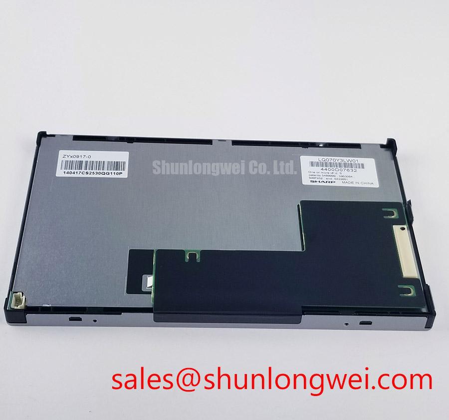
When a warehouse vehicle display returns from humid storage, first separate a visible haze, edge discoloration, or intermittent image from a genuine logic fault by allowing the panel and its harness to reach a stable room condition and ensuring they are free of condensation before powered inspection. The LQ070Y3DG01 is identified here as a Sharp TFT-LCD active matrix color display module; the enclosure, bezel, sealing method, and host mounting arrangement remain system-level considerations rather than confirmed panel specifications.
For AGV and forklift telematics equipment, moisture control begins at the enclosure interface. Inspect the perimeter for compression gaps, trapped contamination, and pressure on the display surface. A panel that has been clamped unevenly can show optical nonuniformity that resembles delamination. Check the flexible cable routing for a gradual bend path, no sharp fold at the connector exit, and sufficient strain relief so vibration is not transferred directly into the contact area.
High-humidity storage at 60°C and 90% RH should be treated as an environmental test condition only when it is specified by the complete equipment qualification plan and is consistent with the module’s documented limits. It is not an automatic rating for this Sharp module. During evaluation, record the appearance before energizing, after temperature stabilization, and after a controlled operating period. A milky edge, expanding bright ring, or persistent local contrast change warrants inspection of the panel perimeter and optical stack, while a complete loss of image requires separate supply, connector, and backlight checks.
Liquid-crystal viscosity changes at sub-zero temperatures can increase visible response lag and produce gray-level transitions that appear slower than normal. That observation alone does not establish permanent damage. Let the module warm naturally within the equipment’s approved environmental limits, then compare a moving grayscale pattern with a known-good signal path. Repeated thermal cycling from −30°C to +85°C should only be applied when those limits are documented for both the module and the complete assembly. Sealant selection, adhesive compatibility, and enclosure pressure equalization should be verified by the system designer.
For a high-EMI vehicle installation, differential routing is a design consideration for any differential host-side link, rather than an LQ070Y3DG01 factory specification. If the host interface uses differential signaling, the board designer should control the pair geometry and skew according to that interface’s requirements. The actual impedance, connector assignment, and acceptable timing margin must come from the relevant interface documentation. The practical objective is to reduce common-mode conversion and preserve eye opening across the harness.
Contrast Evaluation & Liquid Crystal Birefringence Temperature Tracking
Use a controlled grayscale sequence to distinguish temperature-related optical drift from a defective image path. Observe black, mid-gray, and white fields at the normal viewing position, then repeat from the operator’s actual seated or standing angle. This is especially important in forklift cabs, where overhead lighting, windshield reflections, and viewing height can change the perceived contrast without changing the electrical image.
The product data supplied for this listing does not establish an IPS, MVA, or TN optical mode, nor does it confirm a symmetric 85°/85°/85°/85° viewing specification. Those values must not be assigned to the Sharp module without a matching manufacturer document. A replacement decision should therefore compare the original panel’s viewing direction, grayscale behavior, surface finish, and connector arrangement instead of relying on diagonal size or a similar part number.
Temperature changes alter liquid-crystal birefringence and can shift the appearance of dark gray levels before the panel becomes visibly defective. In service, compare the same test image at a cold-start condition and after thermal stabilization. If the change is uniform across the screen, review the environmental and optical conditions first. If it is confined to a band, corner, or line, inspect mechanical loading, cable seating, and the image source before attributing the symptom to the liquid-crystal layer.
Surface glare also affects contrast measurements. A matte or anti-glare treatment should be assessed with the display installed in its real bezel, not with a flashlight or overhead lamp aimed directly at the loose module. The supplied information does not confirm an AG etch, optical bonding construction, or a contrast ratio at 50,000 lux. Such figures belong to a validated optical test report. Sharp’s Sharp Devices Europe provides a manufacturer-level contact point when the original documentation is being matched; the Sharp Display Solutions Official Portal focuses on finished commercial displays rather than panel-specific integration documentation. ([global.sharp](https://global.sharp/products/device/support/call/index.html?utm_source=openai))
For a cross-check during procurement, LQ64D343 may be reviewed as a separate display option, but it should not be treated as a drop-in substitute until dimensions, interface, timing, mounting, optical direction, and backlight requirements have been compared.
Panel Interface Timing, Pixel Clock & Host-Side Differential Links
Do not identify the interface by connector appearance alone. Count the contacts, check the keying and latch orientation, and compare the host cable pin assignment with the panel documentation before applying power. Controller documentation identifies a 32-pin parallel TTL output for LQ070Y3DG01, distinct from the controller’s LVDS output. Do not connect a 20-pin or 30-pin LVDS cable directly on the assumption that it is compatible. Confirm the panel supply, logic levels, pin assignment, and pixel timing against the matching Sharp documentation before connection. ([aitendo3.sakura.ne.jp](https://aitendo3.sakura.ne.jp/aitendo_data/product_img/lcd_controller/Xs/Xs-pinout.pdf?utm_source=openai))
When the host uses a differential video link upstream of a panel-interface converter, inspect that signal route for pair swaps, excessive stubs, shield termination problems, and connector movement under vibration. A split image, unstable color, or repeating vertical pattern can result from mapping errors, timing incompatibility, poor contact, or signal integrity loss. Compare the suspected path with a known-good cable and verify the signal relationship at the receiving end rather than assigning a single cause from the screen symptom.
Power sequencing is equally important. The controller should bring the panel supply and video interface up according to the panel’s documented timing, with reset and enable behavior controlled by the system design. White screen at startup, residual image after shutdown, or delayed recovery can involve supply ramp behavior, backlight enable logic, incomplete discharge, or a controller state that has not reset cleanly. Use an oscilloscope on the host-side test points and compare the sequence with the approved timing information.
Backlight operation must be treated separately from image data. The backlight driver, enable signal, and dimming command must be checked against the module and host documentation rather than assumed from the model number. Do not infer LED construction, brightness lifetime, or a 50,000-hour to 50% brightness decay curve from the model number. For a related system-level comparison, TX18D210VM0BAA can be examined as a separate display solution, not as an automatic electrical companion.
⚠️ Field Alert: Disconnect power and allow the host rails to discharge before inserting or removing the panel cable, because contact movement during an energized connection can disturb signal and supply pins.
Flashlight Dark-Shadow Optical Diagnostic to Isolate Logic vs. Backlight Failure Modes
For a black screen, aim a flashlight across the surface at approximately 45 degrees while the host is commanding a known image. A faint menu, cursor, or color field visible through the dark area suggests that the image path may still be active while the backlight path requires investigation; no visible image calls for separate checks of the controller output, panel power, connector seating, and panel-side response. This test is directional evidence, not a definitive fault code.
Run three controlled fields in sequence: full white, full black, and a primary-color field. Look for a uniform response, fixed lines, localized shadows, or color regions that remain attached to the same physical area. A persistent line or localized defect can involve the panel drive region, cable contact, mechanical stress, or the incoming data path. Avoid pressing the glass or flexible edge during testing, since pressure can change the symptom and complicate diagnosis.
In direct sunlight, perceived contrast depends on surface reflection, viewing angle, bezel geometry, and the actual luminance of the backlight. The supplied baseline does not confirm an optical contrast ratio above 500:1 at 50,000 lux, nor does it confirm optical bonding or a particular anti-glare coating. The equipment designer should validate readability in the installed AGV or forklift display position, including vibration, visor reflections, and long-duration static screens.
Static HMI pages should be rotated or refreshed when the host application permits, because image retention behavior depends on drive conditions, temperature, and operating duration. This is a system design consideration, not a guaranteed characteristic of the module. For enclosure, moisture, and integration practices, the Industrial Display & HMI Solutions guide offers a broader engineering reference without replacing the panel-specific integration record.