Content last revised on October 5, 2026
Flashlight Dark-Shadow Optical Diagnostic to Separate Image and Backlight Faults
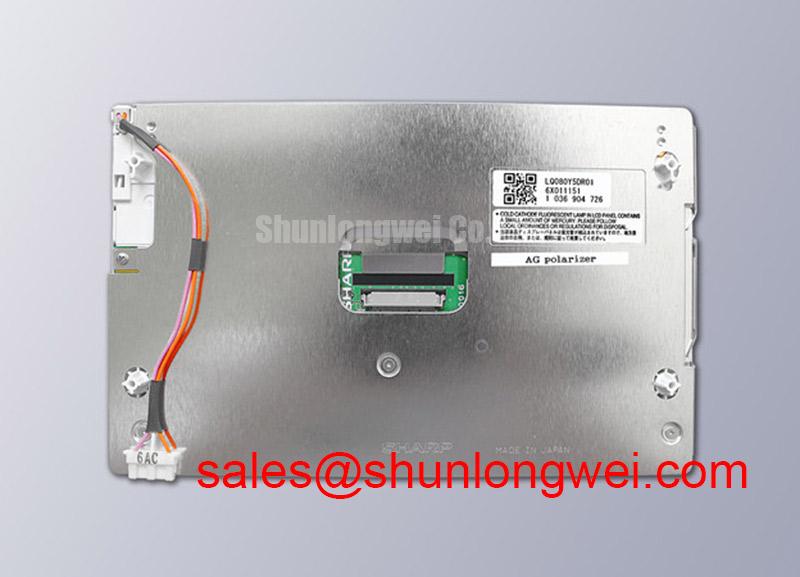
With power isolated, inspect the LQ080Y5DR04 connector and cable seating, then record the module label before tracing the display supply and backlight drive. Sharp identifies this part as an industrial LCD/HMI TFT-LCD display module (Official Factory Specification). The supplied product information does not establish its operating voltage, interface pinout, backlight technology, dimensions or optical ratings, so those details must be checked against the original panel documentation before a repair decision.
For a dark HMI, start at the host rather than treating the panel as the failed part. Confirm that the equipment has completed its normal startup sequence and that the display cable is fully seated at both ends. With the unit operating under the equipment maker’s service procedure, sweep a flashlight across the screen at an oblique angle. A faint but coherent image can suggest that image data is reaching the liquid crystal while illumination is absent or inadequate. No visible image is less conclusive: missing panel power, a disabled host output, an interface fault or a panel fault can produce a similar observation.
Run the host’s primary-color test pattern, if one is available, and note whether red, green and blue appear across the entire active area. Compare the behavior with a known-good signal path before assigning a cause to fixed lines, missing regions or incorrect colors. A line that persists through every pattern warrants inspection of the cable, connector and panel assembly; its appearance alone does not establish a particular internal driver failure. Check the display supply and backlight control signals against the original equipment documentation, using a meter or oscilloscope appropriate to the circuit.
Field Alert: Disconnect equipment power before unplugging or reseating the display cable.
Cold operation deserves a separate observation. As a Design Consideration, liquid crystal response can slow at low temperature, making moving patterns look smeared even when the image path is intact. Let the assembly return to its specified test conditions before comparing response times or replacing hardware. No subzero operating limit, gray-to-gray response rating or heater arrangement is established for LQ080Y5DR04 in the supplied specifications; verify each from the original panel and equipment records.
Chassis Fit and Fastener Loading During Optical Inspection
Before fitting a replacement module, compare the actual outline, active-area position, mounting points, connector location and cable exit with the removed assembly. LQ080Y5DR04 is identified as a TFT-LCD display module, but the supplied specifications do not state a mechanical drawing or fastening torque. Do not apply a torque value borrowed from another display: the equipment chassis, fastener and panel mounting instructions determine the allowable load.
Inspect the image with a uniform dark pattern before final assembly, then repeat the check as the bezel is secured. If a bright or dark patch changes with chassis loading, pause and inspect the seating surfaces, trapped cable and gasket placement. That observation can indicate mechanical stress, but it does not prove a defect in a particular optical layer. As a Design Consideration, distribute mounting pressure evenly and verify the finished image in the equipment’s normal orientation. The acceptable fit and tightening sequence remain system-determined.
View the panel from the operator’s expected positions as well as straight on. Color shift and contrast changes at an angle matter in an HMI, yet no IPS, MVA, viewing-angle or sunlight-contrast rating is established here for this model. Likewise, an anti-glare finish should be confirmed on the actual panel or in its documentation rather than assumed from its industrial designation. For a possible ultrasound diagnostic terminal installation, the equipment engineer should assess readability and mechanical fit against that terminal’s requirements; the module designation alone does not establish suitability for medical use.
When comparing candidates, treat the LM64P10 as a separate part to evaluate, not a confirmed substitute. Compare documented outline, active area, electrical interface, supply requirements and illumination system before considering a change to the equipment configuration.
Backlight Output and Edge-Temperature Checks
If the flashlight check suggests an illumination problem, measure the backlight input and control behavior at the equipment-side connector using the original schematic and service limits. Inspect for intermittent cable contact while watching the backlight command and supply. A stable command with unstable light output narrows the investigation, but the driver, wiring and module still need separate checks. The supplied specifications do not identify the backlight technology or its electrical ratings, so neither a replacement driver nor a drive setting can be selected from the model number alone.
Use a uniform image to look for changes in brightness across the screen after the equipment reaches its normal operating condition. Record whether a dim region stays fixed, changes with warm-up or responds to cable movement. As a Design Consideration, local heating can affect optical uniformity and illumination performance; inspect airflow restrictions and nearby heat sources before changing the chassis. Any proposed heat-spreading rail must be assessed against the module’s mechanical drawing and the equipment’s thermal test results, not assumed to be part of the Sharp assembly.
A luminance-maintenance target or LED lifetime figure cannot be assigned to LQ080Y5DR04 from the supplied information. If an equipment maintenance plan calls for a brightness threshold, establish it from the applicable panel documentation and the system’s measured baseline. For broader enclosure and environmental test planning, Industrial Display & HMI Solutions provides context; acceptance limits for this installation still require the equipment designer’s verification.
Humidity Storage Assessment and Interface Verification
After storage or an enclosure moisture event, inspect the module perimeter, connector and cable for visible residue, corrosion, staining or separation before energizing the equipment. Allow the assembly to reach the equipment maker’s permitted operating conditions, then compare image uniformity and startup behavior with a known-good unit. A visible edge change calls for closer inspection, but it is not enough to identify the internal seal material or predict remaining service life. No humidity-storage limit or thermal-cycle rating is supplied here for LQ080Y5DR04.
Trace the display interface from the host schematic to the panel connector before probing signals. The supplied specifications do not confirm whether this model uses TTL, LVDS or another interface; applying an assumed pinout risks an invalid diagnosis. Once the original documentation identifies the interface, check the prescribed supply sequence, clock, data and enable behavior at the relevant connector. Compare suspect waveforms with a known-good path under the same operating conditions. Signal-integrity limits, including any clock-jitter or data-hold requirements, must come from the applicable panel and transmitter specifications.
If nearby servo equipment coincides with image disturbance, document when the symptom occurs and inspect cable routing, shielding and grounding against the equipment design. As a Design Consideration, interference may enter through the host, cable or power path; a display-only observation cannot establish which path is responsible. Any enclosure sealing, optical bonding or electromagnetic-compatibility claim must be verified for the assembled equipment rather than inferred from this panel’s product category.