Content last revised on October 14, 2026
Tianma TM080SDHG02-41 Display Identification and Replacement Checks
- Disconnect panel power and compare the TM080SDHG02-41 label, connector orientation, and cable routing with the equipment service drawing.
- Inspect the viewing surface, bezel contact points, and dust gasket for contamination, uneven seating, or pressure marks before tightening the display assembly.
- Check the host supply and backlight driver circuits for damaged connectors or abnormal unpowered impedance, using the equipment service procedure rather than an assumed resistance threshold.
- Record the original display settings and inspect enclosure ventilation and moisture exposure before evaluating a replacement.
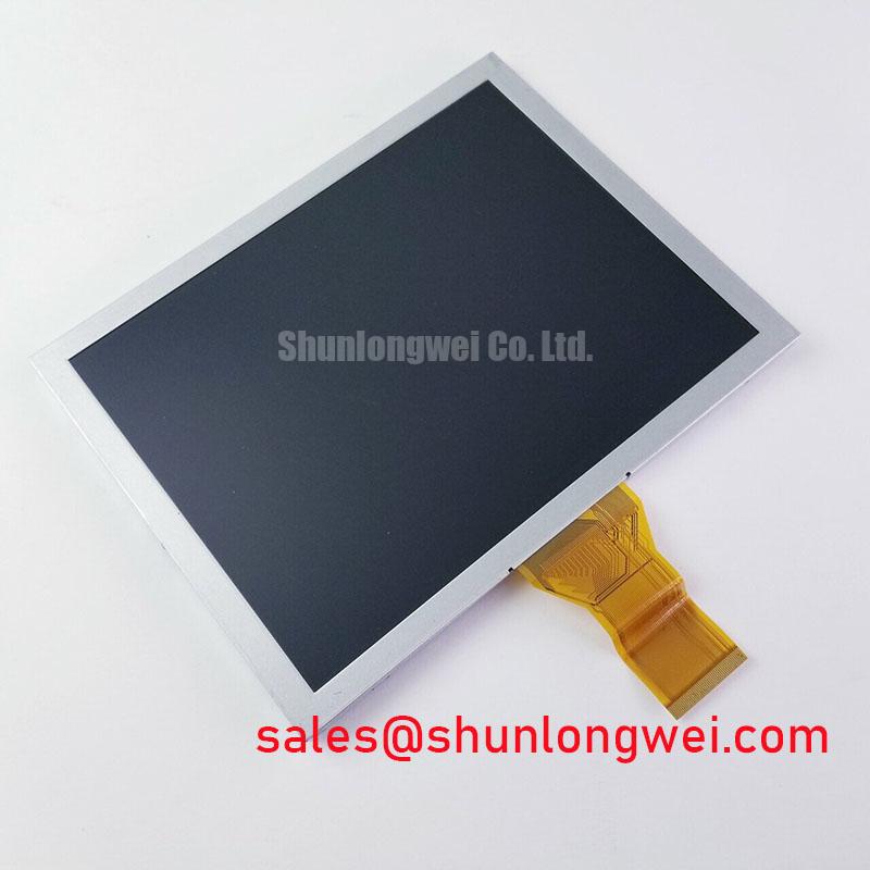
The Tianma TM080SDHG02-41 is identified as an industrial LCD/HMI panel with a TFT-LCD active-matrix color display module construction. Replacement assessment should start with the complete model suffix, mechanical drawing, and electrical interface specification—not the apparent similarity of the screen opening.
| Product identity | Specification baseline |
|---|---|
| Model | TM080SDHG02-41 |
| Manufacturer | Tianma |
| Product category | Industrial LCD/HMI panel |
| Module construction | TFT-LCD active-matrix color display module |
| Electrical, optical, dimensional, and environmental ratings | Consult the model-specific datasheet. |
Assessing Anti-Glare (AG) and Anti-Reflective (AR) Treatments for High Ambient Readability
Inspect a dark image under the actual installation lighting, then change the viewing angle to separate reflected glare from changes in grayscale reproduction. Design Consideration: AG treatment scatters reflected light, while AR treatment reduces reflection through an optical coating system; these are different mechanisms, and neither treatment should be attributed to this module without its optical specification.
A protective window can alter the result substantially. Compare the panel with and without the enclosure window, keeping image content and illumination consistent. Reflections between surfaces, accumulated cleaning residue, and window haze can reduce useful contrast even when the display itself operates correctly. Avoid abrasive cleaning or solvents outside the approved cleaning procedure.
Viewing-angle assessment should include dark-gray transitions, text edges, and warning colors at the intended operator positions. TN grayscale inversion and IPS or MVA viewing behavior are general technology distinctions, not an identification method for the TM080SDHG02-41. A broad viewing cone also does not establish symmetric color or contrast performance. Manufacturer optical information from Tianma Microelectronics Industrial TFT Displays provides useful context for interpreting those characteristics.
Engineering Recommendation: If the external backlight driver supports PWM dimming, compare its control waveform with optical output across the usable brightness range. Check for low-duty instability, visible flicker, and audible driver noise under actual operating conditions. Dimming frequency and control polarity belong to the approved panel-driver combination; a generic frequency range cannot establish compatibility or flicker-free operation.
Logic Supply Voltage Sequencing and Driver IC Latch-Up Risks
Match the host supply to the panel pin definition before connecting the display harness, and capture startup and shutdown at the panel connector rather than only at the power supply. Design Consideration: Supply sequencing helps limit unintended powering through signal pins, but does not independently guarantee freedom from latch-up. The required supply voltage must be verified from the model-specific electrical specification.
Compare the measured rail ramp, signal-enable timing, and backlight-enable timing with the approved sequence. Look for interrupted ramps during repeated starts and for signals remaining active after the panel supply collapses. Probe loading and ground placement matter: a measurement arrangement that disturbs the circuit can obscure the transient being investigated.
For an interface documented as LVDS, check pair assignment, polarity, receiver requirements, and connector continuity before changing controller settings. Differential impedance and skew limits should come from the transmitter, receiver, and interconnect specifications. Preserve pair coupling and avoid unnecessary discontinuities; validate the assembled cable path rather than treating a nominal routing target as proof of signal integrity.
JEIDA and VESA mapping becomes relevant only when the approved interface uses those conventions. Incorrect mapping can affect color or grayscale reproduction, while split images can also involve timing, channel configuration, or connection faults. Compare a controlled test pattern with the known-good host configuration before assigning a cause.
During host-controller or backlight-driver evaluation, the TCG070WVLPCANN-AN00 is a separate display solution for comparison, not a backlight driver or confirmed companion component. For equipment using an LED constant-current driver, assess current regulation, enable behavior, and documented open-load or short-circuit protection through that driver's specification and approved test procedure.
Thermal Expansion Clearance Sizing across Heavy Industrial Metal Enclosure Cutouts
Check clearance around the panel assembly before compressing the bezel gasket, paying particular attention to corners, cable exits, and mounting points. Design Consideration: The enclosure, mounting frame, and display assembly can expand differently as temperature changes. Clearance should accommodate the specified dimensional tolerances and operating conditions without allowing the panel to become a structural load-bearing member.
Support the assembly at its intended mounting features and tighten fasteners progressively using the equipment's approved sequence and torque. A generic screw-size torque is not a panel mounting limit. Inspect a uniform dark and gray image before and after fastening; a change in local brightness can warrant investigation of seating pressure, gasket thickness, or bracket distortion, rather than an immediate diagnosis of panel failure.
Maintenance Note: Periodically inspect ventilation paths and gasket seating so dust accumulation or displaced seals do not compromise cooling or apply uneven pressure to the display.
When evaluating compatibility for a CNC operator panel or robot teach pendant, compare the full mechanical envelope, connector access, viewing orientation, and host configuration. The TX17D02VM2CAA-2 can enter that comparison as a separate candidate, but it is not established here as a direct replacement for the TM080SDHG02-41. Matching appearance alone does not establish interchangeability.
Cold-start assessment should distinguish slow liquid-crystal response from host timing faults. Compare motion and grayscale settling after thermal stabilization within the documented operating range. Prevent condensation during transfers between cold storage and warmer humid areas using the equipment's environmental handling procedure. Any response compensation must remain within the panel-controller specification.
Backlight brightness retention and MTBF describe different outcomes; neither supports a service-life claim without defined conditions and supporting evidence. Track brightness at consistent settings and temperature when maintenance records require comparison. The Industrial Display & HMI Solutions engineering resource provides broader context for enclosure integration and environmental evaluation.
Radiated Emissions Assessment, Backplate Bonding, and Grounding
Compare display behavior with nearby switching equipment inactive and operating, then inspect the cable route and enclosure bonding before altering the panel configuration. Design Consideration: Horizontal noise bands or pixel instability can involve conducted interference, signal-integrity problems, supply disturbance, or grounding faults; the symptom alone does not identify the source.
Shield termination should follow the equipment's EMC design and connector construction. Where a shielded cable is specified, preserve its intended enclosure connection and minimize unintended gaps in the return path. Multipoint bonding and star grounding are different arrangements; combining their names does not define an effective high-frequency topology. Evaluate the actual return paths and chassis connections.
A common-mode suppression component should be considered only after identifying the disturbance path and checking its effect on the wanted signal. Cable separation, connector seating, and supply filtering may require attention first. Verify changes through repeatable measurements rather than treating disappearance of a visible artifact as evidence of compliance.
CISPR emissions classification belongs to the tested equipment configuration, not to this LCD module independently. Assess sunlight readability separately by measuring the assembled display under defined illumination, viewing geometry, and brightness settings. Record both the optical result and the interference-test configuration so subsequent repairs can reproduce the relevant acceptance checks.