

Content last revised on October 8, 2026
Radiated Emissions Compliance via Backplate Multi-Point Star Grounding
When a cab display develops pixel jitter, horizontal noise bands, or intermittent image loss near a variable frequency motor drive, begin with the physical signal path rather than changing the panel immediately. Inspect the display frame, cable shield termination, controller enclosure, and backplate bonding points. A 360-degree shield connection is a system-level installation method, not a confirmed factory feature of this Sharp module. The integrator should verify whether the installed FFC, LVDS harness, or transition board actually provides continuous shielding and whether the chassis has a controlled return path.
A practical railway repair sequence is to document the original cable routing, separate display data wiring from motor and brake power wiring, and inspect every connector latch for incomplete engagement. A shield pigtail that has become loose can increase common-mode noise even when the display connector appears fully seated. Where the equipment design permits it, engineers may evaluate a common-mode ferrite at the cable entry, but its impedance curve, current rating, and placement must be selected from measured interference results. It should not be treated as a guaranteed solution for this model.
CISPR Class A or Class B performance belongs to the completed equipment and installation. The LQ104V7DS01 display module itself should not be described as independently certified for the emissions performance of a railway cab or passenger information system. During validation, use the known-good signal path as the reference and inspect the display clock, data transitions, chassis potential, and cable shield continuity while the traction or auxiliary drive is operating. An oscilloscope and near-field probe can help distinguish a signal-integrity problem from a power-ground disturbance.
Cold operation adds another diagnostic variable. Liquid crystal response can become slower at sub-zero temperatures, but no specific cold response time or compensation value is confirmed in the supplied data for this model. If the equipment operates around −20°C to −30°C, the system designer should verify the actual panel operating range, startup timing, heater control, and image response using a thermal chamber or controlled cold-start test. A heater strip may reduce startup delay, but it also introduces local thermal gradients and must be evaluated with the bezel, diffuser, and cable routing installed.
For background on signal integrity, optical behavior, and industrial panel integration, engineers can consult The Ultimate Guide to Industrial TFT LCD Technology. Use that technical reference as a design aid while retaining the original Sharp documentation as the authority for model-specific limits.
Viewing Direction and Grayscale Inversion Mitigation
A railway display may appear acceptable during a bench test and become difficult to read when installed at the driver’s position or behind a passenger information enclosure. The first check is the viewing direction. TN panels can show a stronger contrast shift or grayscale inversion when viewed away from their preferred axis. The supplied data does not confirm the panel cell type, viewing-angle values, surface treatment, or normally white optical mode for LQ104V7DS01. These characteristics must be confirmed from the original Sharp panel documentation rather than inferred from the model family.
At the workbench, display a grayscale ramp and inspect it from the actual cab viewing position, including the vertical angle created by the bezel. Repeat the check with the intended cover glass, anti-glare window, and ambient illumination. A nominally clear image can lose useful tonal separation when sunlight, tunnel lighting, or cab reflections reach the surface. If the display is used for passenger information, check readability from the expected standing and seated positions instead of relying on a single central viewing point.
IPS or MVA replacement panels may offer a wider and more symmetrical viewing cone, sometimes specified in design literature with values such as 85 degrees in four directions. That is a comparative design consideration, not a specification for this Sharp model and not an automatic justification for substitution. An alternative such as LMS700KF01-001 should be assessed through connector mapping, active-area dimensions, mounting features, optical direction, signal timing, and backlight requirements before the equipment owner approves any change.
The video interface also requires measured validation. Do not assume TTL or LVDS from the TFT-LCD category alone. Confirm the transmitter type, lane arrangement, clock polarity, pixel order, data hold behavior, and power-up sequence from the original controller and panel documents. If the image shows occasional noise, compare the clock and data waveforms at the panel connector against a known-good unit. A visible grayscale fault can result from viewing angle, timing margin, cable integrity, or controller configuration, so the panel should not be condemned from the visual symptom alone.
For long-term HMI use, static symbols and fixed status bars deserve a separate inspection. LCD image retention can be influenced by panel construction, drive conditions, temperature, and extended static content. The supplied factory information does not establish a guaranteed retention or burn-in limit for this model. Designers should use screen rotation, controlled dimming, or periodic content movement only where those functions are permitted by the railway human-machine interface specification and do not compromise operational clarity.
Industrial Bezel Mechanical Envelope Tolerances and Mounting Screw Torque
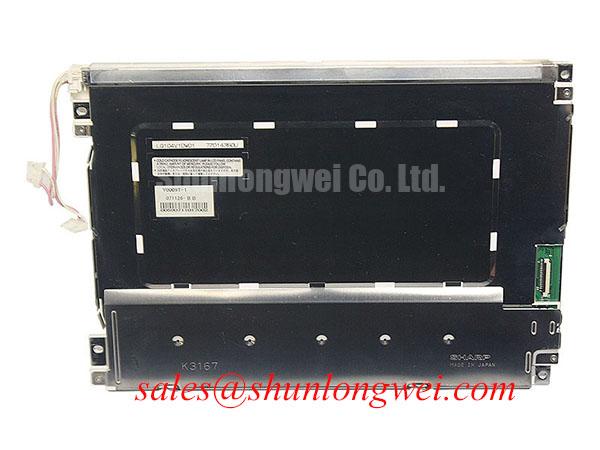
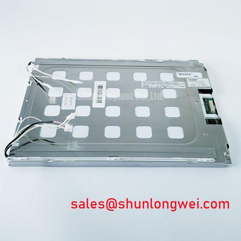
Before removing the failed display, photograph the bezel, gasket, mounting brackets, cable bend radius, and fastener locations. Measure the opening and record the position of the active image area relative to the chassis. The supplied data identifies LQ104V7DS01 as a TFT-LCD display module but does not confirm its outer dimensions, mounting-hole pattern, active area, connector position, or bezel thickness. A replacement that fits the aperture can still place stress on the glass, flex cable, or optical stack.
For a metal chassis using M3 fasteners, a cross-pattern tightening range of 0.35 to 0.45 N·m may be used only as a general mechanical design consideration when approved by the equipment manufacturer and compatible with the bracket, gasket, and fastener materials. It is not an official factory torque specification for this Sharp model. Tighten progressively while checking for bezel distortion, uneven gasket compression, and changes in the dark-field image. A rigid bracket that transfers railway vibration directly into the panel can create intermittent connector faults even when the screws remain tight.
⚠️ Field Alert: Disconnect equipment power and allow the display supply to discharge before inserting or removing the panel cable; a live connector operation can damage the panel interface or controller.
Use strain relief at the chassis entry and keep the flexible cable away from sharp edges, heater surfaces, and moving service doors. Do not fold the FPC at the connector root. During vibration maintenance, inspect for whitening, creases, latch wear, and cable migration. A connector that passes a static continuity check can still lose contact under vibration if the locking mechanism or cable support is poor.
High-EMI installations also require controlled differential-pair routing. A nominal 100 ohm ±10 percent differential impedance and a skew target of 50 ps or less can be treated as system design targets where specified by the controller and interface standard, not as confirmed internal characteristics of LQ104V7DS01. The actual cable, connector, transition board, and PCB stack-up determine the result. Validate the complete path with the appropriate test fixture and compare eye opening or waveform quality at the panel-side connector.
Do not apply adhesive, foam, or additional thermal pads behind the display without checking clearance and pressure distribution. Localized loading may create visible non-uniformity, especially after the panel warms from cold startup. The correct repair method is to restore the original support points and gasket compression, then verify the image with white, black, red, green, blue, and grayscale test screens.
Constant Luminance Output Control and Backlight Reliability Verification
When a railway display is reported as dim, first separate a panel optical problem from a backlight power problem. Inspect the backlight driver, input fuse, harness, connector contacts, and brightness command while comparing the failed unit with a known-good assembly. The available factory information does not confirm the backlight technology, LED current, luminance rating, PWM frequency, L70 value, or B50 lifetime for LQ104V7DS01. Those figures must not be assigned to the model without the relevant Sharp data sheet.
For a system using PWM dimming, a control range between 200 Hz and 1 kHz can be evaluated as a typical starting window for visible flicker and camera interaction, but it is not a factory recommendation for this module. The driver must be checked for minimum pulse width, current regulation, acoustic behavior, thermal rise, and compatibility with the railway controller. If the display is filmed by an inspection camera, test the actual camera exposure and frame rate rather than judging flicker by eye alone.
Thermal inspection is most useful at the edge of the display and around the backlight driver. A narrow aluminum heat-spreader rail may be considered when the mechanical design permits it, but its contact pressure, electrical isolation, thermal interface material, and enclosure airflow must be verified. The purpose is to reduce local hot spots without loading the panel glass or obstructing the FPC. No specific heat-spreader size, thermal resistance, LED junction temperature, or operating-life value is confirmed for this model.
L70 and B50 are reliability metrics that require a defined test method, temperature, drive current, sample population, and acceptance condition. They should be obtained from the manufacturer or an authoritative qualification document before being used in a railway maintenance prediction. Do not convert a generic LED lifetime statement into a guaranteed operating period for the complete display assembly. For field service, record brightness setting, ambient temperature, backlight driver output, thermal images, and the time pattern of dimming complaints.
Cold-start testing should include the complete assembly rather than the bare panel. At sub-zero temperature, allow the enclosure, cable, controller, and backlight driver to stabilize before applying the normal startup sequence. Verify whether the image initially shows slow transitions, uneven illumination, or delayed backlight activation, then confirm recovery as temperature rises. The correct compensation strategy is system determined and may involve heater timing, display enable sequencing, or brightness control, subject to the original equipment safety and operating requirements.