



Content last revised on September 24, 2026
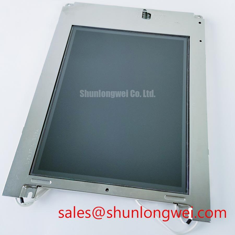
Sharp LQ9D011K TFT LCD Display Module
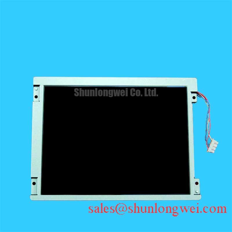
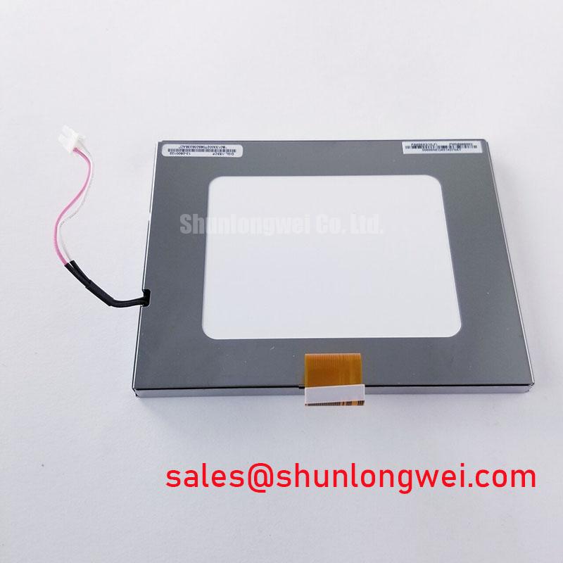
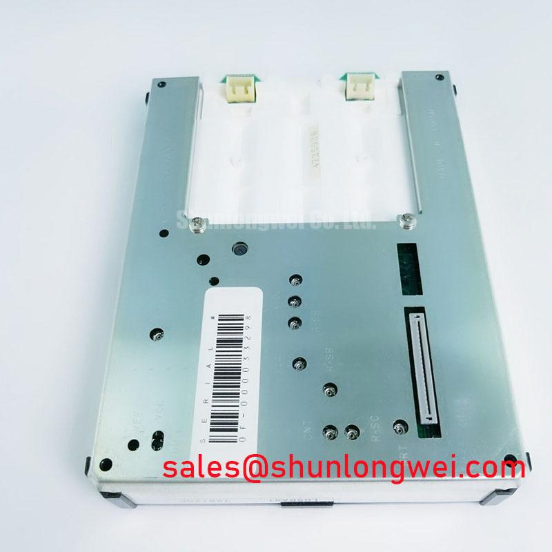
Before fitting the LQ9D011K, inspect the TFT LCD display module housing, viewing surface, connector area, and attached flexible cable for handling damage, trapped debris, distortion, or connector latch wear, then compare the removed unit with the original equipment documentation before applying power.
The Sharp LQ9D011K is identified as an Industrial Grade LCD/HMI Panel in a TFT LCD Display Module enclosure. Its listed status is Official Factory Spec Verified. The available verified information identifies the product category and manufacturer, but does not establish electrical input voltage, display size, resolution, interface type, backlight technology, luminance, operating temperature, mounting dimensions, or connector pin assignment. The system integrator should verify these requirements from the original panel documentation and the host equipment schematic before replacement or new integration.
| Item | Verified Information |
|---|---|
| Model | LQ9D011K |
| Manufacturer | Sharp |
| Product Category | Industrial Grade LCD/HMI Panel |
| Module Form | TFT LCD Display Module |
| Specification Status | Official Factory Spec Verified |
For repair work, retain the original display assembly until the replacement has passed a controlled bench check. Confirm connector position, cable routing direction, mechanical seating, mounting reference points, active image orientation, and the host controller’s expected signaling convention. A panel with a visually similar footprint can still be electrically unsuitable if its timing format, supply sequence, or illumination control arrangement differs from the original assembly.
Thermal Cycling Review of Polarizer Adhesives and Perimeter Seal Interfaces
Thermal cycling assessment begins with a physical inspection rather than assumptions about environmental qualification. Examine the front polarizer for edge lifting, local discoloration, surface waviness, pressure marks, or zones where contrast changes across the image. Inspect the perimeter interface between the display structure and surrounding bezel for signs of moisture ingress, accumulated dust, adhesive movement, or a mounting frame that applies uneven pressure. These observations help establish whether a visual fault may relate to the panel assembly, the enclosure, or external mechanical loading.
At low ambient temperature, liquid crystal response can become slower, so transitions between grey levels can appear delayed until the assembly stabilizes. This is a display behavior to evaluate at the actual equipment temperature, not a verified operating limit for the LQ9D011K. At elevated temperature, prolonged static imagery may make pre-existing optical nonuniformity more noticeable. A controlled test should display black, white, red, green, blue, and moving grey patterns while the equipment is observed across its intended environmental range.
For industrial HMI enclosures, the display module should be mounted so that the bezel and fastening method support the module without twisting it. Excessive clamping force, hard contact against an uneven frame, and cable strain transferred into the display connector can create intermittent artifacts that resemble panel damage. Design Consideration: allow the mechanical stack to accommodate normal enclosure movement from temperature change while keeping dust and moisture paths away from the display edge.
Interface integrity requires the same discipline. The available verified product information does not specify whether the LQ9D011K uses LVDS, TTL, or another data interface, so no signal protocol should be presumed. Where a host design uses differential display signaling, impedance continuity, pair length matching, correct shield termination, and alignment with the controller’s required JEIDA or VESA mapping are system-level checks. A picture with incorrect color order, unstable pixels, or a shifted image can result from mapping or timing disagreement, not necessarily from a defective LCD module.
Potential evaluation for passenger information displays or cab signalling displays should remain conditional on the original equipment interface, enclosure sealing, and approval requirements. For broader inspection methods involving industrial display assemblies, Industrial Display & HMI Solutions provides a relevant technical reference point for maintenance planning.
Suppressing Acoustic Noise and Electromagnetic Disturbance in the Illumination Path
Do not assume the illumination technology or dimming method of the LQ9D011K from its model designation alone. The original panel documentation must establish the required backlight supply, enable logic, brightness control input, electrical limits, and power sequencing. A replacement module can show a stable image signal while remaining dark, excessively bright, unstable, or intermittently illuminated if the host backlight circuit and the module requirements are not correctly matched.
Acoustic noise near a display is often attributed to the panel when the actual source can be an external power conversion stage, an inductor, a capacitor, a mechanical resonance in the enclosure, or cable vibration. Isolate the source with the display assembly safely installed and compare the sound during brightness changes, static images, and known stable power conditions. If the noise changes with dimming command activity, inspect the illumination driver path and its mounting. If it changes with nearby motor operation, examine grounding, cable placement, and coupling into the display power harness.
Design Consideration: keep sensitive display signal paths separated from noisy motor, relay, and power conversion harnesses where the equipment layout permits. Shield termination should follow the host equipment design because a shield connected in an unsuitable way can alter noise behavior rather than improve it. The final arrangement should be checked in the assembled cabinet, with the actual load conditions that produce the disturbance.
Optical readability should also be evaluated as an installed system property. Front window material, anti-glare treatment, enclosure recess depth, ambient reflections, and the condition of any protective overlay can affect contrast more than the panel alone. The verified specification provided for the LQ9D011K does not state a contrast ratio, sunlight readability rating, anti-glare coating, brightness rating, or illumination lifetime. These properties should therefore be checked against the original display requirement instead of being inferred.
When reviewing related display assemblies and supporting hardware, LM64P10 can be considered as a separate product reference for system-level sourcing review. It must not be treated as an electrical or mechanical substitute for the LQ9D011K without a full documentation-based compatibility check.
Single Vertical Hairline Defect and Image Path Fault Localization
A narrow vertical line, a repeated column anomaly, a partial image, or an apparently dark region should be tested with controlled patterns before the panel is removed. Feed the known host image source or a validated display test source, then observe full red, green, blue, black, white, and moving grey content. Record whether the artifact is fixed to the same screen location, whether it follows a cable movement, whether it changes after the equipment reaches thermal equilibrium, and whether it is visible in the host system’s diagnostic display output.
A fixed line can be associated with the panel image path, but it can also be influenced by connector contact, flex cable stress, display controller output, timing mismatch, or external interference. A dark display can involve the image source, power sequence, illumination path, brightness control, or the display itself. The practical goal is to separate a repeatable panel-localized observation from a system-dependent symptom. Testing against a known good signal path is more reliable than deciding from one visual symptom alone.
Use a low-intensity oblique light source only as a visual aid for identifying surface scratches, front layer defects, bezel shadowing, or local pressure damage. It is not a definitive method for determining internal failure mechanisms. Avoid pressing on the display surface to make a line disappear or reappear, because mechanical pressure can worsen an existing defect and makes a controlled diagnosis less reliable.
🔧 Bench Diagnostic: Disconnect or reconnect the display cable only after the host equipment is fully powered down and its documented discharge procedure has been completed.
Long-duration HMI use may involve static icons, status bars, route maps, warnings, or fixed control graphics. Where image retention is observed, evaluate the host user interface, display timing, brightness setting, duty cycle, and thermal environment together. The verified information for this model does not define image retention performance or an approved static image duration. System designers should use the equipment’s display management strategy and qualification method to evaluate long-term image behavior.
For a replacement assessment based on dimensional class, resolution class, interface, and mounting arrangement, the LM190E08-TLG6 is a separate reference item. Its suitability must be established through documented comparison of every relevant mechanical, optical, electrical, and signaling requirement.
Shielded Flexible Cable Grounding and Connector Retention Near Variable Speed Drives
Flexible cable handling deserves attention during every panel replacement. Follow the original cable bend direction, avoid pulling on the conductor tail, and ensure that any connector lock is fully engaged without forcing it. A cable that appears seated can still have uneven contact if the latch is damaged, the cable is inserted at an angle, or the assembly is strained by a tight routing path. After reassembly, inspect whether cabinet movement, vibration, or service access pulls on the cable or presses it against a sharp edge.
In cabinets containing variable speed drives, contactors, switching supplies, or high-current conductors, horizontal noise bands and pixel jitter may indicate noise coupling into display wiring. They may also arise from controller timing instability, grounding discontinuity, illumination power disturbance, or a degraded cable assembly. Evaluate the display with the noisy equipment inactive and active, then compare behavior while observing the known good reference path. This provides more useful evidence than assigning a single cause from the screen appearance.
Where the equipment uses a shielded display cable, the shield and connector shell arrangement should remain consistent with the original equipment grounding architecture. A full connector shell contact can improve high-frequency continuity only when the enclosure, cable, and controller grounding strategy support it. Design Consideration: minimize exposed unshielded cable length near noise sources and verify the completed installation under real switching conditions.
Power sequencing must also be confirmed from the original panel documentation and host board design. Applying data before the required supply state, interrupting illumination control in an unexpected order, or using a mismatched enable level can produce a blank screen, transient image behavior, or residual display artifacts. The correct sequence is system-determined and should be verified with the documented controller timing rather than estimated from similar Sharp display modules.
For equipment that may be evaluated in railway passenger information systems or cab signalling displays, compatibility review should include physical mounting, display visibility, interface behavior, cable retention, enclosure conditions, and the applicable system approval process. The LQ9D011K Sharp TFT LCD Display Module should be treated as a documented replacement candidate only when those equipment-specific checks agree with the original assembly.