

Content last revised on October 29, 2026
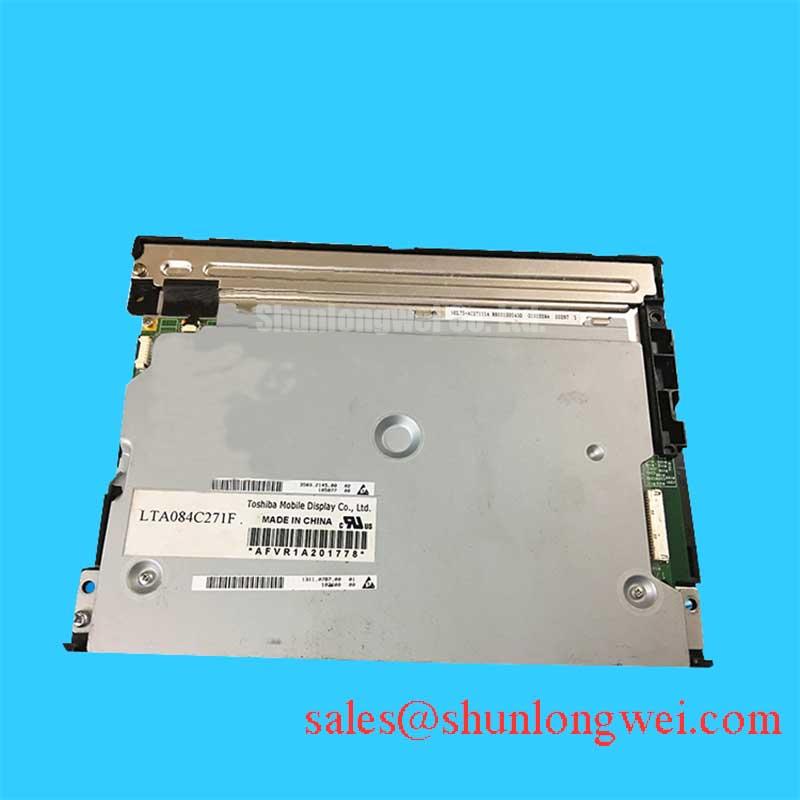
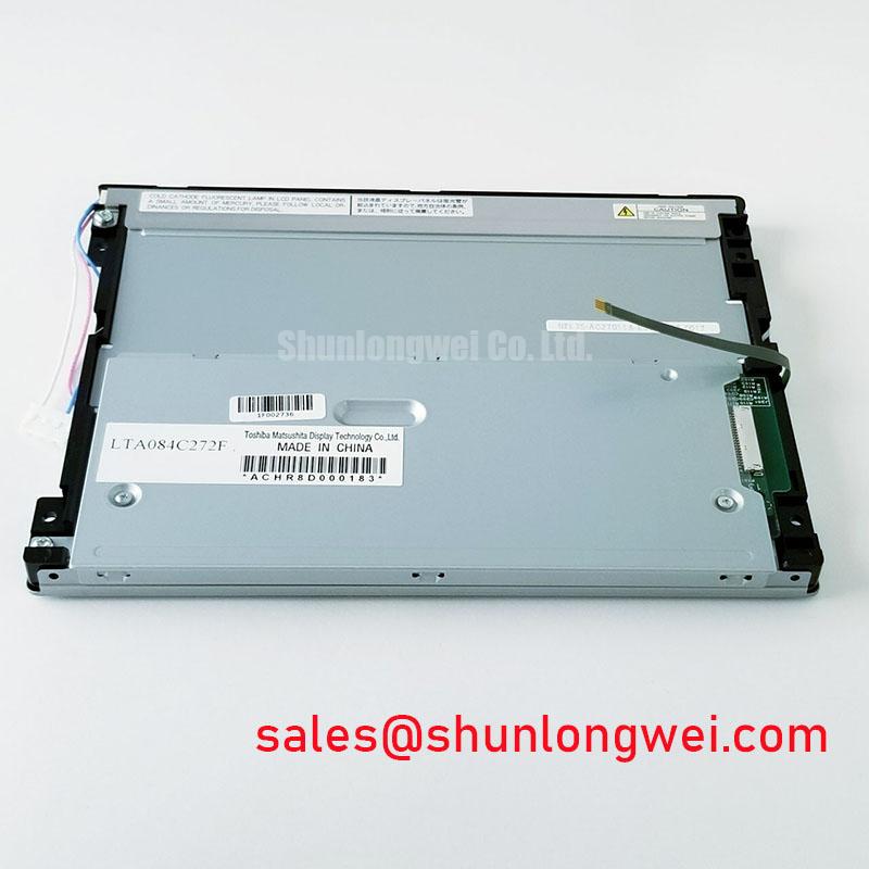
LTA084C272F Samsung Industrial TFT LCD Display Panel
- Confirm the panel marking and the replacement part number before removing the original display.
- Inspect the FPC, connector lock, edge seal, and mounting surfaces under controlled lighting.
- Check the host controller documentation for interface voltage, timing, data mapping, and backlight requirements.
- Compare the active image area, bezel clearance, and cable exit direction with the CNC or robot pendant enclosure.
The LTA084C272F is identified as a Samsung TFT LCD Active Matrix Color Display Module for evaluation in industrial display and HMI integration. The available product information does not establish a complete electrical timing table, backlight configuration, industrial temperature rating, or mechanical drawing, so those values should remain part of the host equipment compatibility check rather than being assumed during replacement.
| Manufacturer | Samsung |
| Model | LTA084C272F |
| Display type | TFT LCD Active Matrix Color Display Module |
| Interface, resolution, and optical ratings | Consult Datasheet |
For a CNC operator panel or robot teach pendant, the replacement decision should begin with physical and signal compatibility. A panel that fits the opening can still require different timing, pin assignment, connector orientation, or backlight control. The Samsung model should therefore be compared with the removed unit at the enclosure, cable, and controller levels before installation.
Aluminum Heat Spreader Sizing and Thermal Interface Placement Along Narrow Display Edges
Heat spreader rails should be evaluated along the narrow display edges when the enclosure places heat producing electronics close to the panel perimeter. The purpose is to distribute local heat into a mechanically stable path while avoiding pressure on the glass, FPC, or connector region. This is a Design Consideration, not an identified factory specification for the LTA084C272F.
During incoming inspection, illuminate a full white image and then a mid gray field. Observe the edge zones for brightness variation, localized color shift, or a visible transition between the active area and the bezel. Repeat the check after the panel has reached the enclosure operating condition. A rail should not touch the active glass unless the original mechanical design explicitly provides for that contact. The interface should remain even, free from particles, and isolated from cable folds that could transfer mechanical stress into the panel edge.
Outdoor or high ambient installations require a separate optical review. An application contrast target of more than 500:1 at 50,000 lux should not be treated as an official rating for this model without a supporting Samsung datasheet. Instead, the system integrator should measure readability with the final cover window, surface treatment, viewing direction, and enclosure lighting in place. Anti glare behavior depends on the complete optical stack, so a replacement panel should be assessed through the actual front surface rather than by relying on a catalogue description alone.
General TFT operating principles are outlined in the Thin Film Transistor Liquid Crystal Display technology reference. For broader industrial display comparisons, the Winstar TFT LCD module reference provides useful context, but it does not define the Samsung model’s own ratings.
Normally White TN Grayscale Inversion Mitigation and Optimal Viewing Direction Alignment
Viewing direction should be established from the installed operator position before selecting a replacement for grayscale critical work. If the original panel uses a normally white TN arrangement, grayscale inversion can become visible when the operator moves above, below, or to the side of the intended axis. The available LTA084C272F information does not confirm the liquid crystal mode or viewing angle, so IPS or MVA behavior must not be assumed.
Display the actual CNC status screens, alarm messages, tool paths, and robot position graphics during the optical check. Examine dark gray text on a light background and light text on a dark background from the normal standing or handheld viewing direction. Look for changes in character weight, shadow detail, and alarm color separation. Surface anti glare treatment can reduce reflections under workshop lighting, yet excessive diffusion may soften small text. The correct balance is determined by the installed cover, ambient light, and operator distance.
Backlight modulation also belongs to the host system verification plan. A proposed PWM range such as 200 Hz to 1 kHz is an example evaluation range for visible flicker and audible interaction in a complete display assembly, not an official LTA084C272F specification or a guarantee of flicker-free operation. Check brightness linearity across the controller’s command range and observe the panel through a camera as well as directly. If the replacement uses a different backlight control method, the system integrator should verify the original panel documentation before applying a drive signal.
💡 Bench Tip: Protect the panel from ESD and insert the FPC squarely before locking the connector, because a partially engaged cable can create intermittent image faults that resemble a display timing problem.
Evaluating Low-Temperature Image Response in Cold Storage and Outdoor Industrial Facilities
Low temperature testing should focus on image response after the panel has stabilized in the intended enclosure, not immediately after power is applied. Liquid crystal viscosity generally increases as temperature falls, which can lengthen gray to gray transitions and leave moving characters or tool paths visibly smeared. This physical behavior is a Design Consideration; the available product data does not provide a confirmed LTA084C272F response time or industrial temperature rating.
Use a moving grayscale pattern, scrolling alarm text, and rapidly changing numerical fields to assess the actual operator interface. Compare the display at room condition with the planned low temperature condition, paying attention to dark to light transitions and the recovery of small text after a screen change. A heater strip may be considered only when the enclosure designer has established a safe thermal strategy and validated the complete assembly. It should not be presented as a standard accessory of this Samsung module.
For outdoor equipment, inspect the perimeter, frame contact, and cable exit after thermal cycling. Look for separation, discoloration, condensation, or mechanical movement around the seal and bezel. An evaluation range of minus 30°C to plus 85°C should be used only when it matches the equipment qualification plan and the applicable panel documentation. It is not an official rating established by the available product information.
Reducing static image retention also requires interface management. CNC status pages and robot pendant menus that remain unchanged for long periods should be reviewed through the host software strategy, including periodic changes to displayed content or screen blanking where operationally appropriate. These measures are system recommendations and do not establish a guaranteed retention performance for the panel.
For enclosure level thermal and optical practices, the engineering reference Built to Last can be used as a related design resource.
Controlled Differential Flex Routing to Suppress High Frequency Jitter
FPC routing should preserve the original cable path, bend direction, connector seating depth, and strain relief arrangement. Avoid folding the cable across a sharp enclosure edge or trapping it beneath a frame rail. Repeated service movement in a robot teach pendant can transfer force into the connector, so the cable should be supported by the enclosure rather than by the panel contacts.
A host design that uses a 100 ohm differential characteristic impedance should treat that value as a system routing requirement, not as a confirmed specification of the LTA084C272F. The PCB trace geometry, cable construction, connector, return path, and termination must be assessed together. Use an oscilloscope or suitable signal integrity fixture to compare the replacement assembly with a known good display path when split screen artifacts, unstable pixels, or intermittent frame loss appear.
Power sequencing also needs direct comparison with the original controller. The available information does not confirm whether this model requires a 3.3 V or 5.0 V logic supply, nor does it confirm a power rise interval such as 0.5 ms to 10 ms. The system integrator should verify the required supply voltage and timing from the original panel documentation, then check for white screen behavior, delayed image start, residual frames, and abnormal backlight activation during repeated power cycles.
JEIDA and VESA data mapping are not interchangeable assumptions. Confirm the connector pinout and bit mapping before enabling the panel, then inspect color bars, grayscale ramps, and full screen red, green, and blue fields. If a same size or same resolution replacement is being evaluated, the LT084AC27500 should be compared through its own documented interface and mechanical data rather than treated as a direct electrical substitute.