


Content last revised on September 10, 2026
AUO M170EG01 V7 Industrial LCD Panel for SCADA Display Integration
At incoming inspection, place the M170EG01 V7 on an ESD-safe bench, examine the glass and frame under uniform illumination, and confirm the label against the approved equipment documentation before applying power. This procedure helps separate visible shipping damage, connector contamination, and configuration mismatch before the panel enters a high-voltage substation protection or SCADA dispatch console.
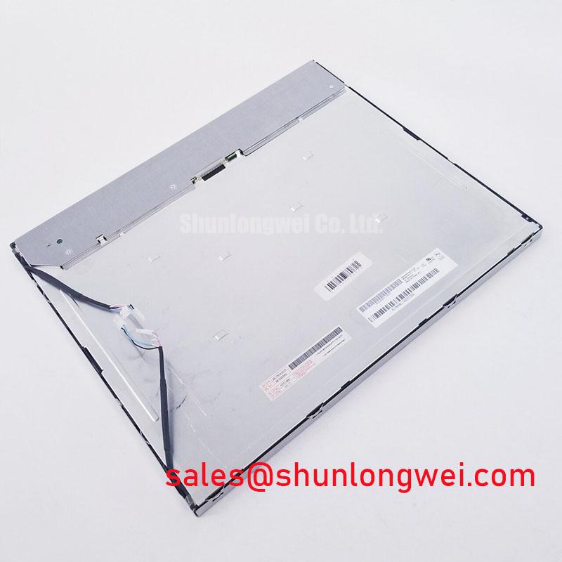
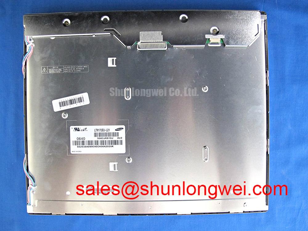
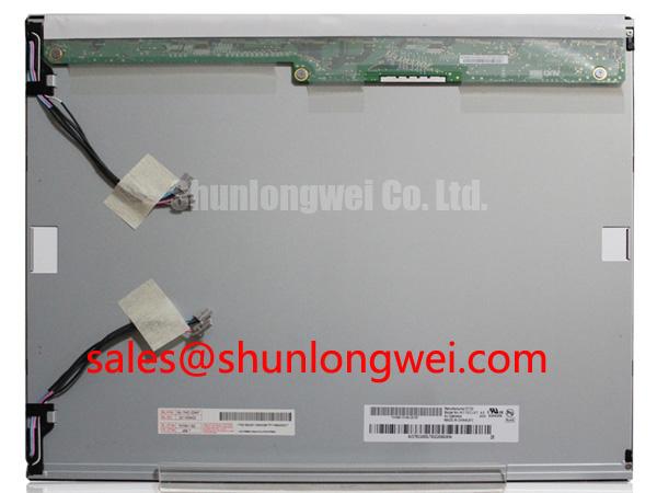
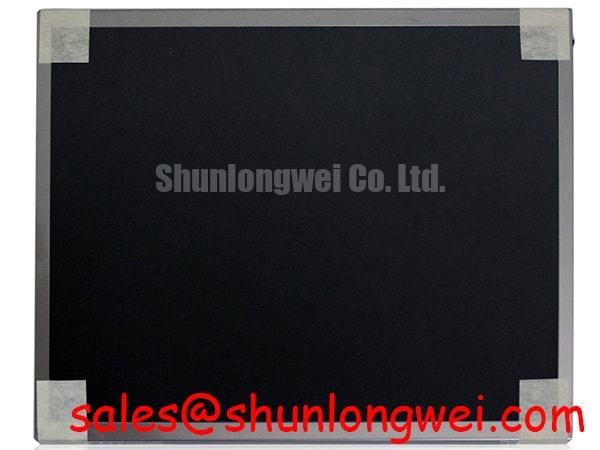
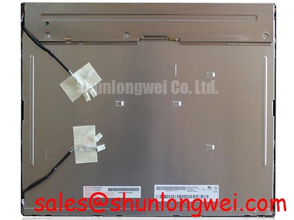
The M170EG01 V7 is identified as an AUO Industrial Grade LCD/HMI Panel in a TFT-LCD Display Module package. The available factory context verifies the product category, manufacturer, module construction, and model identification. Detailed electrical timing, optical performance, interface mapping, backlight type, dimensions, and environmental limits should be checked against the original AUO documentation or the documentation used in the host equipment.
| Attribute | Verified information |
|---|---|
| Model | M170EG01 V7 |
| Manufacturer | AUO |
| Product category | Industrial Grade LCD/HMI Panel |
| Package or construction | TFT-LCD Display Module |
| Specification status | Detailed model specifications require verification against applicable AUO documentation |
For a replacement assessment, engineers should compare the original panel’s active area, resolution, mounting points, connector position, signal format, backlight configuration, and controller compatibility. A matching diagonal size alone does not establish electrical or mechanical interchangeability. If the original service record identifies another panel family, the M185XW01 VE can be reviewed as a separate same-class display option, subject to a complete dimensional and interface comparison.
Managing Localized Thermal Gradients During Long-Term Display Operation
Thermal inspection around a display opening should begin with the enclosure, nearby power supplies, ventilation path, and any heater or defroster element. A narrow hot region at one edge of the panel can create a visible brightness or color difference even when the display electronics remain functional. This is a system-level condition, not an official performance specification of the M170EG01 V7, so the final assessment should use measured enclosure temperatures and the original panel documentation.
Design Consideration: An aluminum heat-spreader rail may be evaluated along a constrained display edge when the mechanical design produces a repeatable local temperature rise. The rail should be mechanically isolated from exposed conductors and should not place pressure on the glass, bezel, flex cable, or mounting tabs. Its effectiveness must be verified with the panel operating in the completed enclosure rather than on an open laboratory bench.
Color drift should be checked with a full-screen white field, neutral gray fields, and several saturated colors. A calibrated colorimeter can help identify whether the change is global or localized. Visual inspection alone may miss a gradual shift that becomes obvious beside a known-good reference panel. Record the display state, enclosure condition, ambient temperature, and warm-up period so that repeated measurements remain comparable.
The supplied product information does not verify PMMA optical material, LED L70 or B50 values, or a guaranteed optical yellowing threshold for this model. Those figures should not be assigned to the panel without an applicable factory source. When the console operates in a cold room, the integrator should also observe gray-to-gray motion after cold soak. Liquid-crystal response can change with temperature, and any heater-strip control strategy must be validated against actual image behavior, power consumption, and enclosure safety requirements.
For a substation protection or dispatch console, inspect the display while status pages, alarm banners, trend graphics, and switching diagrams are active. These screens expose uneven luminance and slow transitions more clearly than a static logo. A thermal camera or contact sensor may be used to compare the perimeter, center, connector region, and adjacent control electronics, while ensuring that the measurement method does not obstruct normal airflow.
Evaluating Backlight and High-Voltage Interface Compatibility
Do not assume a replacement panel uses the same backlight architecture as the removed unit. The available factory context for M170EG01 V7 does not confirm CCFL operation, LED operation, ignition voltage, driver topology, PWM dimming performance, acoustic behavior, or service-life data. The system integrator should verify the required backlight supply and control signals from the original panel documentation before connecting an inverter or LED driver.
If the host assembly uses a high-voltage cold-cathode backlight circuit, inspection should include the inverter connector, cable insulation, transformer area, grounding arrangement, and clearance from the metal chassis. A high-voltage test is a system safety activity and must follow the equipment manufacturer’s approved procedure, using a suitable instrument and controlled isolation. A claimed striking-voltage range cannot be treated as an M170EG01 V7 factory rating without an applicable datasheet.
Where the host equipment uses an LED backlight, verify the driver’s current regulation, enable logic, dimming input, connector pinout, and fault response against the replacement panel requirements. A constant-current output that is electrically suitable for one panel can be unsuitable for another if the feedback method, LED string arrangement, or protection behavior differs. PWM frequency and duty-cycle behavior should be evaluated on the complete display assembly, especially where operators view fine grid lines, alarm text, or rapidly changing measurements.
Acoustic noise should be checked with the cabinet doors closed and open, because resonance from the enclosure can make a driver or inverter appear louder in the installed console. Listen during startup, minimum brightness, maximum brightness, and transitions between display pages. This is a practical diagnostic observation rather than proof of a particular component failure. If noise appears, compare the driver waveform, mechanical mounting, cable routing, and load compatibility with the approved service design.
The available product information does not establish a greater-than-50,000-hour half-life or MTBF value for this model. Procurement and maintenance records should therefore use the manufacturer’s applicable specification rather than a generic backlight-life claim. 💡 Bench Tip: Disconnect power and allow the approved discharge interval before handling the display cable, then insert the flex cable squarely and lock it without lateral force.
Assessing Cold-Temperature Response and Thermal-Cycle Behavior
When the panel is considered for an unheated control room or an outdoor-facing operator station, the first task is to verify the actual temperature range in the original AUO documentation. The supplied product data does not confirm an operating range of −30°C to +85°C for the M170EG01 V7. That range may be relevant to a system qualification plan, but it must not be presented as a factory limit for this specific model without supporting documentation.
At low temperature, slower liquid-crystal movement can appear as extended gray-to-gray transitions, especially in dark-to-light changes and moving numerical data. The correct evaluation uses a controlled thermal chamber, a repeatable test pattern, and a defined observation method. Engineers should compare startup behavior after cold soak, image transitions during warm-up, and recovery after the panel returns to room temperature. A subjective “looks slow” observation is useful for screening but is not a substitute for the timing limits required by the host system.
Thermal cycling should also include inspection of the perimeter seal, frame attachment, flex connection, and any mounting interface that could transfer stress into the glass. The internal sealant chemistry and construction of this AUO module are not confirmed in the supplied data, so no specific epoxy material or stability claim should be assigned. Look for changes in display uniformity, edge leakage, intermittent lines, or connector sensitivity after the approved qualification sequence.
A heater strip may be considered where the equipment specification requires rapid cold recovery. Its control must be designed around the complete enclosure, available power, sensor location, thermal spread, and operator-surface limits. Designers should verify that heating does not create a localized gradient or interfere with the backlight and controller. Any PWM setting for a heater or backlight should be selected by the system engineer after checking flicker perception, acoustic behavior, electromagnetic interaction, and the requirements of the installed driver.
For field troubleshooting, compare a cold-start image with a known-good panel using the same source, cable, controller, and brightness command. If only one region changes, inspect mechanical pressure and local temperature before replacing the panel. If the entire image changes, verify the source timing, power rails, backlight control, and enclosure conditions. This measured approach is consistent with the practical methods described in The Ultimate Guide to Industrial TFT LCD Technology.
Verifying TTL RGB Synchronization and Logic Power Requirements
Before connecting the M170EG01 V7 to a controller, identify the exact interface from the original panel documentation and the host board schematic. The available factory context does not confirm TTL 24-bit RGB, a 3.3 V or 5.0 V logic rail, JEIDA or VESA mapping, a defined power-on rise-time window, or a 100-ohm differential interface. These items must be verified rather than inferred from the panel model or connector appearance.
For a TTL RGB implementation, inspect the pixel clock, horizontal and vertical timing, data-bit order, display-enable behavior, and ground allocation. A mapping error can produce incorrect colors, unstable graphics, or an image that appears divided even though the panel is illuminated. Use the original controller configuration where possible, then confirm the signal relationship with an oscilloscope or logic analyzer at the panel-side connector. Probe loading and cable length should be controlled so that the measurement does not create the fault being investigated.
Power sequencing deserves the same care. Confirm the logic supply voltage, backlight enable order, reset behavior, and required delays from the applicable panel specification. The figures 0.5 ms to 10 ms should not be applied to this model unless the AUO documentation explicitly assigns them to the relevant timing parameters. During startup testing, monitor the supply at the panel connector rather than relying only on the controller-board test point.
Route high-speed display conductors away from noisy switching nodes, provide a continuous return path where the system design permits, and keep connector seating consistent between test units. If the host actually uses differential signaling, the integrator should verify the specified characteristic impedance and termination from the interface documentation; TTL RGB itself should not be described as a differential bus. Final acceptance should use the installed cable, controller, enclosure, and ambient-light condition.
For a high-voltage substation protection or SCADA dispatch console, validate the panel with live alarm graphics, numerical readouts, mimic diagrams, and trend views. Confirm that changes in the source frame rate, brightness command, or backlight enable do not introduce intermittent artifacts. Optical contrast, anti-glare performance, and sunlight readability also require documented panel data and completed-system testing; the supplied information does not verify a contrast ratio above 500:1 at 50,000 lux.