Content last revised on October 15, 2026
Industrial EMI Noise Immunity, Chassis Shielding Continuity & Common-Mode Ferrite Chokes
When pixel jitter or horizontal noise bands appear near a variable-frequency motor drive, inspect the complete display signal path before replacing the panel. For M270DAN01-0, begin with the chassis bonding path, connector seating, cable routing, and the continuity of any cable shield from the display enclosure to the controller enclosure. A shield that terminates through a narrow pigtail or loses contact at a painted mounting surface can allow common-mode noise to enter the display interface even when the panel itself remains electrically functional.
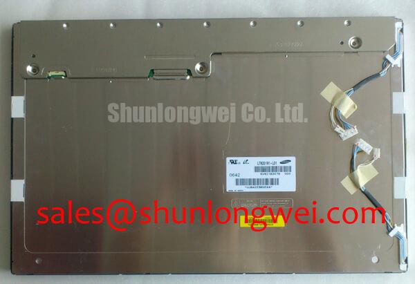
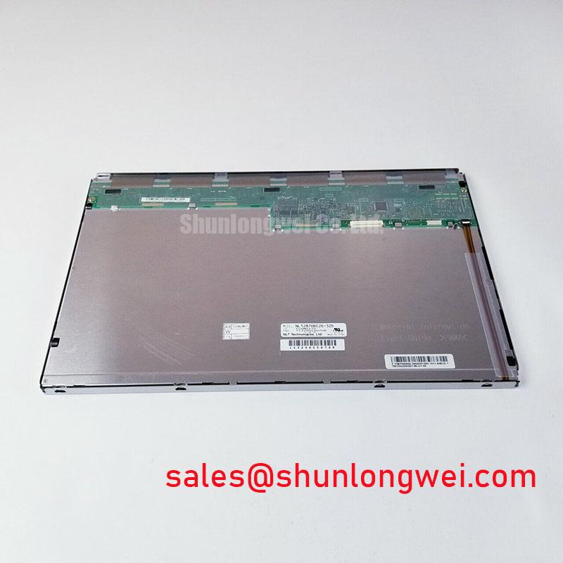
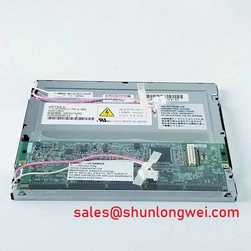
The display is an AUO TFT-LCD active-matrix color display module. The supplied listing does not establish an industrial environmental qualification, panel-specific interface pin map, logic supply, backlight current, or contrast rating. The system integrator should verify those values and the exact model designation against the original panel documentation before connecting a replacement. Do not infer connector orientation or signal order from a mechanically similar panel.
For a noisy installation, maintain a continuous chassis reference around the display opening and keep high-current motor wiring physically separate from the display cable. A common-mode ferrite choke may be evaluated as a system-level interference-control measure when the noise is present on both conductors of a differential pair. Its impedance profile must be assessed against the interface signal spectrum, cable length, and receiver tolerance; adding an unsuitable choke can increase edge distortion and reduce timing margin.
Direct ambient light should be evaluated using the actual cover glass, viewing angle, and enclosure geometry. The supplied product context does not confirm a panel-specific optical contrast value or anti-glare coating, so those characteristics should be checked against the original display assembly. The AUO website provides useful manufacturer-level context for comparing display families, but it does not replace the model-specific interface documentation.
💡 Pro Tip: Keep the differential display pair closely coupled and length-matched through the complete cable route, then verify signal integrity at the receiver while the motor drive operates through its normal switching range.
High-Humidity Storage & Delamination Prevention Protocols
Humidity-related display faults often develop at interfaces rather than at the visible image area, so inspect the perimeter, connector region, cover interface, and enclosure drainage path after high-humidity storage. For this model, avoid treating a generic environmental label as proof of resistance to condensation, delamination, or seal degradation. The supplied product context does not provide a model-specific humidity qualification or thermal-cycle rating.
In a sealed control console, moisture can remain trapped after a rapid temperature transition. The resulting optical haze, uneven transmission, or intermittent image behavior should be compared with a dry reference unit and observed during controlled warm-up. If the assembly uses optical bonding, examine the bond perimeter for changes in uniformity or trapped moisture without pressing the active area. Mechanical pressure can create a temporary optical change that obscures the original fault.
Low-temperature operation also affects liquid-crystal response. Increased viscosity can lengthen gray-to-gray transitions, producing visible trailing or delayed refresh without proving that the timing controller has failed. If the documented operating range permits sub-zero testing, compare identical test patterns at the same frame rate and record whether the delay follows temperature, image content, or the host timing source.
Confirm the documented interface type before evaluating timing and data mapping. For panels that use TTL or LVDS, the transmitter clock, data hold interval, polarity, and data mapping must remain compatible with the receiving controller. JEIDA and VESA LVDS data formats are not interchangeable assumptions. Confirm the original mapping before commissioning, particularly where a replacement produces a stable backlight but incorrect colors, shifted grayscale, or a white image. Power-up and power-down sequencing should also be compared with the panel and controller specifications to reduce the risk of transient white-screen behavior or residual image artifacts.
For broader enclosure, grounding, and harsh-environment integration guidance, review Industrial Display & HMI Solutions. The page-level application should still be judged by the actual seal design, cable entry, ventilation strategy, and condensation control of the host equipment.
Aluminum Heat Spreader Sizing & Thermal Interface Placement along Narrow Display Edges
Thermal inspection should concentrate on narrow edge zones, backlight driver areas, and locations where the display frame contacts the enclosure. An aluminum spreader rail can distribute localized heat, but its dimensions, attachment method, and contact pressure are system-dependent. It should not obstruct the active area, compress the glass, or create a rigid mounting condition that transfers enclosure distortion into the panel.
Use a compliant thermal interface only where the mechanical stack-up permits controlled contact. The interface should be thin enough to avoid stressing the display and continuous enough to prevent isolated hot spots. Designers should confirm the contact pattern with thermal imaging during sustained operation, because a visually uniform image does not demonstrate uniform backlight or driver temperature.
The supplied product information for M270DAN01-0 does not confirm a specific LED architecture, optical sheet construction, backlight lifetime rating, or L70/B50 value. Do not assign a backlight current or PWM frequency from a different panel in the same mechanical family. The original controller and backlight documentation should establish whether brightness is controlled by PWM, analog command, enable gating, or a dedicated driver interface.
Where PWM dimming is used, assess duty-cycle linearity, visible flicker, audible interaction with the driver, and camera-band artifacts across the intended brightness range. A suitable frequency is determined by the backlight driver, LED electrical response, camera exposure conditions, and the visual requirements of the HMI. The system engineer should validate the complete display assembly rather than judging the panel in isolation.
Static industrial HMI screens also require image-content management. Alternate layouts, controlled dimming, and appropriate screen blanking can reduce persistent image retention, but no universal prevention interval can be assigned without the panel construction and operating profile. Keep the thermal path stable while testing these measures so that optical changes are not confused with temperature-dependent behavior.
Flashlight Dark-Shadow Optical Diagnostic to Isolate Logic vs. Backlight Failure Modes
A dark screen should first be separated into a logic-path fault and a backlight-path fault. In a controlled bench test, apply primary-color patterns through the known-good controller and inspect the panel in normal illumination. Then place a flashlight at an oblique angle to the surface and look for a faint image shadow. A visible image under the dark condition can indicate that image data and liquid-crystal modulation are present while the backlight path requires further examination; it does not identify one failed component by itself.
Use red, green, and blue test fields together with a neutral gray pattern. Uneven color blocks, vertical line defects, or regions that remain unchanged across patterns should be compared with the signal output at the controller and with a known-good display. This approach helps distinguish mapping errors, timing incompatibility, connector contact problems, and localized panel defects without assigning a single cause from one symptom.
At low ambient temperature, gray-to-gray response can become visibly slower because the liquid crystal responds differently to the same drive waveform. A heater strip must not be assumed to be part of this display module. If the host equipment uses one, its control loop, insulation, and thermal distribution should be evaluated separately from the panel interface. Excessive local heating can create optical nonuniformity or mechanical stress at the perimeter.
For a suspected driver or bonded-edge defect, rotate test patterns and observe whether the line or dark region remains fixed in panel coordinates. Intermittent changes during cable movement require careful connector and harness inspection, while persistent coordinate-locked defects warrant comparison with the panel’s original service history. Avoid flexing the glass or bonded edges during this test.
Power must be removed before disconnecting or inserting the display cable; hot-plugging can damage the panel interface or controller.