Content last revised on September 28, 2026
MCC132-18IO1 Product Identification and Replacement Review
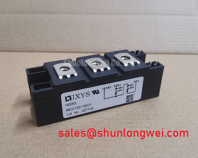
Verify the module marking against the service record, inspect the case and terminals for mechanical damage, and confirm the original circuit boundary before applying test voltage. The IXYS MCC132-18IO1 is a Dual Thyristor Module with an official rated voltage of 1800.0 V, an official rated current of 132.0 A, and a module package. These are the confirmed product-level specifications available for procurement and initial equipment assessment.
For a grid-tied Static Var Compensator or thyristor-switched capacitor assembly, the replacement decision must also account for gate-drive timing, semiconductor fuse coordination, cooling conditions, terminal geometry, and the original control topology. The rating alone does not confirm interchangeability. Designers should verify the complete circuit and the applicable IXYS documentation before installation.
Benchtop Waveform Tuning: Mitigating Stress via Critical Rate of Rise of Off-State Voltage on MCC132-18IO1
Begin waveform work with the module disconnected from the energized system and use an isolated measurement arrangement suitable for the circuit voltage. A dual thyristor module can be exposed to an off-state voltage transition created by transformer leakage inductance, capacitor switching, wiring inductance, or another semiconductor in the same commutation path. If the transition is excessive or poorly damped, unintended triggering and localized current concentration may occur. The correct response is measurement first, followed by controlled adjustment of the snubber and switching network.
An RC snubber is a Design Consideration rather than a confirmed factory value for this specific model. The system engineer should select the resistor and capacitor from measured switching waveforms, capacitor bank behavior, allowable losses, and the actual thyristor control scheme. A series saturable reactor may also be evaluated where the installation requires controlled current rise during capacitor energization. Its suitability depends on the system impedance, switching frequency, fault protection, and the thermal behavior of the complete assembly.
During bench testing, capture the gate signal and main-terminal voltage together with the load current. Check whether the gate pulse reaches the correct terminal pair, whether its width is sufficient for reliable triggering under the intended operating conditions, and whether the control circuit produces a stable pulse train under the intended phase angle. The MCC132-18IO1 data supplied for this product page does not include confirmed IGT or VGT values, so those limits must be taken from the applicable manufacturer datasheet rather than inferred from the 132 A rating.
Terminal identification, polarity, and mounting orientation should be matched to the original wiring record. The parallel reference part PD104VT2T1 may be reviewed as a separate same-family reference, but it should not be treated as an automatic substitute without checking electrical, mechanical, and gate-drive compatibility.
Benchtop Waveform Tuning: Mitigating Stress via Surge Energy Dissipation and Clamping Voltage on MCC132-18IO1
For a thyristor-switched capacitor or SVC branch, assess the complete AC input protection path before replacing the power module. Surge current can enter through the supply network, capacitor bank, transformer coupling, or switching transients. MOVs, RC snubbers, line reactors, semiconductor fuses, and upstream disconnects each address different portions of the disturbance. Their coordination should be reviewed against the actual line voltage, prospective fault current, repetitive switching duty, and enclosure thermal conditions.
IEEE 61000-4-5 testing may be relevant to the equipment-level surge study, but compliance of the finished apparatus cannot be assigned to the MCC132-18IO1 alone. The module is a power component, not an independent EMC or safety certification. The integrator should select the clamping arrangement using verified MOV energy data, working voltage, pulse repetition, and the measured surge waveform. The selected clamp must not create excessive leakage or unwanted conduction during normal operation.
When a replacement is installed in a capacitor-switching branch, record the pre-existing protection arrangement before changing any component value. A different snubber capacitance or MOV rating can alter switching loss, leakage current, resonant behavior, and the voltage seen by neighboring devices. Verify the peak terminal voltage with an appropriately rated differential probe and compare it with the manufacturer’s confirmed repetitive and non-repetitive voltage limits.
The PD104SL7 can be considered as a separate front-end or complementary power-stage reference during topology review. It does not establish compatibility with the MCC132-18IO1, and its electrical role must be confirmed from the original SVC schematic.
MCC132-18IO1 Circuit Protection & Reliability: Calibrating I2t Sub-Cycle Melting Rating
Semiconductor fuse coordination is a central service check when a 132 A dual thyristor module is used in a high-energy AC branch. The fuse must interrupt the fault before the module exceeds its permitted non-repetitive surge or short-circuit withstand condition. The required comparison uses the fuse manufacturer’s clearing I2t data and the applicable IXYS thyristor withstand data under the actual fault waveform. No fuse I2t value is specified in the product information supplied here, so a numerical coordination result cannot be assigned to this model.
Record the installed fuse manufacturer, part number, voltage class, prospective current, and coordination category. Then compare the fuse’s total clearing behavior with the device data for the relevant half-cycle or sub-cycle event. Consider the effects of capacitor discharge, transformer impedance, source asymmetry, and repeated switching. A fuse that appears suitable from its continuous current rating may still be unsuitable for the available fault energy or the capacitor discharge path.
Inspection after a protective event should include the module body, terminals, busbars, fuse holder, snubber components, gate wiring, and surrounding insulation. Measure the control path against a known-good reference circuit and use an oscilloscope where the gate pulse or commutation behavior is uncertain. Avoid assigning a single cause from a visible fuse opening or a failed thyristor; the fault sequence can include a protection-device failure, abnormal gate drive, excessive surge, or a thermal problem.
Long-term reliability claims require application-specific testing and source documentation. No FIT rate, single-event burnout rate, cosmic-ray limit, operating-life figure, or altitude derating value is established by the supplied product parameters. Those subjects should be handled through the manufacturer’s qualification documents and the equipment owner’s environmental assessment. The broader power-electronics context can be reviewed in Future of Power Electronics.
Benchtop Waveform Tuning: Mitigating Stress via Baseplate Thermal Resistance on MCC132-18IO1
Thermal inspection should begin with the heatsink, contact surface, mounting hardware, airflow path, and evidence of compound drying or displacement. The official product information confirms a module package, but it does not provide a verified thermal resistance value, baseplate dimensions, mounting torque, or heatsink specification. These values must be obtained from the applicable IXYS mechanical and thermal documentation rather than estimated from the 132 A rating.
As a Design Consideration, the mounting surface should be clean, flat, and free of burrs. Apply only the thermal interface material and installation method approved for the module and heatsink combination. Uniform clamping pressure helps maintain contact across the baseplate; excessive or uneven pressure can distort the package or stress the ceramic assembly. The system engineer should verify the manufacturer’s tightening sequence and torque before final assembly.
Measure temperature at comparable operating points and inspect the airflow path during scheduled maintenance. A rising case-to-heatsink temperature difference may justify checking contact pressure, compound condition, heatsink fouling, fan performance, and current sharing. It does not by itself identify one failed component. ⚠️ Maintenance Note: De-energize and discharge the equipment before touching terminals, and periodically check heatsink cleanliness, contact temperature, and airflow direction.
Control-panel displays can support trend monitoring, but the display specification remains separate from the power module. Industrial HMI selection may be reviewed through Winstar Industrial TFT-LCD and OLED Display Modules; a general explanation of amorphous silicon TFT technology may also assist display-system evaluation. Neither source establishes the electrical or thermal limits of the MCC132-18IO1.